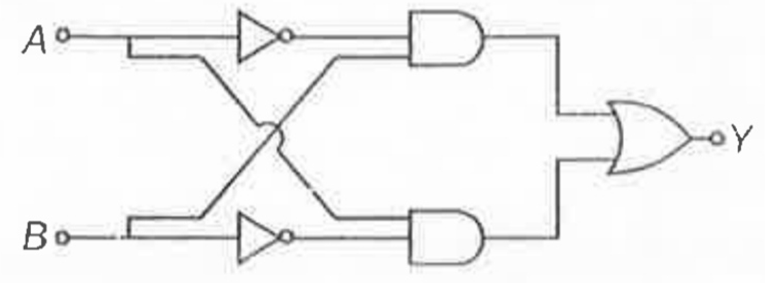
The logic circuit (figure) represents which logic gate?

A
NAND gate
B
AND gate
C
XOR gate
D
NOR gate
Video Solution
Text Solution
The correct Answer is:C
|
Answer
Step by step video & image solution for The logic circuit (figure) represents which logic gate? by Physics experts to help you in doubts & scoring excellent marks in Class 12 exams.
Updated on:21/07/2023Topper's Solved these Questions
Similar Questions
Knowledge Check
The logic circuit Fig. represents
 ANAND gate with outlet, O=¯¯¯X+¯¯¯YBNOR gate with outlet, O=¯¯¯¯¯¯¯¯¯¯¯X+YCNAND gate with outlat, O=¯¯¯¯¯¯¯¯X.YDNOR gate with outlet, O=¯¯¯X.¯¯¯Y
The circuit given below represents which of the logic operations ?
 AANDBNOTCORDNOR
The circuit given below represents which of the logic operations ?
 AANDBNOTCORDNOR
