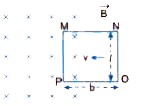
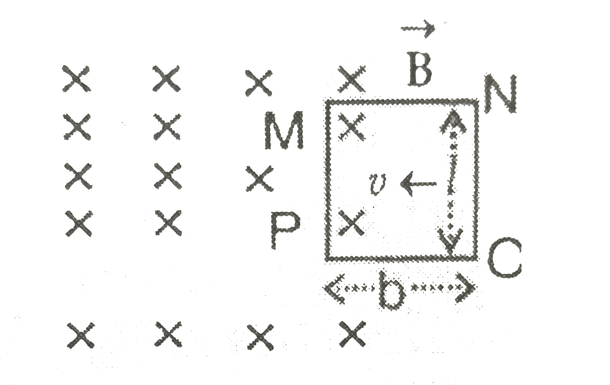
The figure shows a rectangular conducting frame MNOP of resistance R placed partly in a perpendicular magnetic field →B and moved with velocity →v as shown in the fig. 6.52.
Obtain the expressions for the
(a) force acting on the arm 'ON' and its direction, and
(b) power required to move the frame to get a steady emf induced between the arms MN and PO.

As the rectangular frame MNOP moves into the magnetic field, magnetic flux linked with the frame increases at a rate Δϕ=BΔA=BvlΔt and hence magnitude of induced emf
∣∣ɛ∣∣=ΔϕΔt=BvlΔtΔt=Bvl
As resistance of frame is R, hence induced current I=ɛR=BlvR The induced current flows in an anticlockwise direction i.e., along ONMPO.
(a) The force acting on the arm ON is given by
F=∣∣I→l×→B∣∣=IlB=BlvR.lB=B2l2vR
The force is directed opposite to the direction of v (i.e., towards right).
(b) Power required to move the frame to get a steady emf induced between the arms MN and PO,
Powre P=Fv=B2l2v2R
Topper's Solved these Questions
- ELECTROMAGNETICE INDUCTIONBOOK - U-LIKE SERIESCHAPTER - ELECTROMAGNETICE INDUCTIONEXERCISE - Long Answer Questions -II
9 Videos
- ELECTROMAGNETICE INDUCTIONBOOK - U-LIKE SERIESCHAPTER - ELECTROMAGNETICE INDUCTIONEXERCISE - Self Assessment Test (Section -A)
5 Videos
- ELECTROMAGNETICE INDUCTIONBOOK - U-LIKE SERIESCHAPTER - ELECTROMAGNETICE INDUCTIONEXERCISE - Short Answer Questions
38 Videos
- ELECTROMAGNETIC WAVESBOOK - U-LIKE SERIESCHAPTER - ELECTROMAGNETIC WAVESEXERCISE - SELF ASSESSMENT TEST (SECTION C)
1 Videos
- ELECTROSTATIC POTENTIAL AND CAPACITANCE BOOK - U-LIKE SERIESCHAPTER - ELECTROSTATIC POTENTIAL AND CAPACITANCE EXERCISE - SELF ASSESSMENT TEST
1 Videos
Similar Questions
The figure shows a rectangular conducting frame MNOP of resistance R placed partly in a perpendicular magnetic field →B and moved with velocity →V as shown in the figure.
Obtain the expressions for the
(a) force acting on the arm 'ON' and its direction, and
(b) power required to move the frame to get a steady emf induced between the arms MN and PO.

View SolutionThe figure shows arectangular conducting frame MNOP of resistance R placed partly in a perpendicular magnetic field →B and moved with velocity →V as shown in the figure.
Obtain the expressions for the
(a) force acting on the arm 'ON' and its direction, and
(b) power required to move the frame to get a steady emf induced between the arms MN and PO.

View Solution
Knowledge Check
A metallic rod completes its circuit as shown in the figure. The circuit is normal to a magnetic field of B=0.15 tesla. If the resistances of the rod is 3Ω the force required to move the rod with a constant velocity of 2m/sec is-
 A3.75×10−3NB3.75×10−2NC3.75×102ND3.75×10−4N
Fig. 12.32 shows a long, rectangular, conducting loop of with l, mass m and resistance R placed partly in a perpendicular magnetic field B. With what velocity should it be pushed downwards so that it may continue to fall wihtout any acceleration?
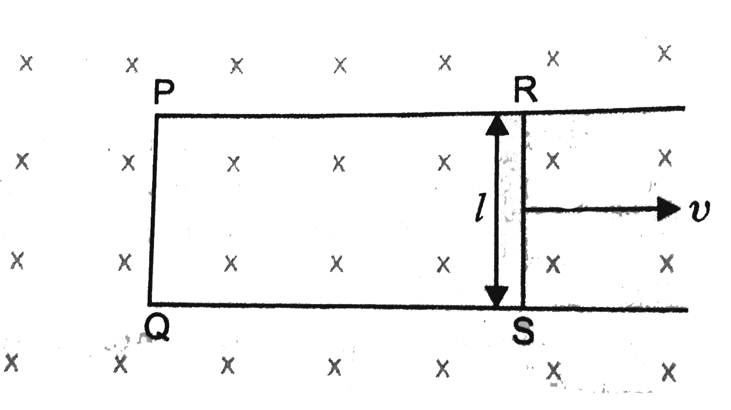
View SolutionFig. shows a rectangular conducting loop PQSR in which arm RS of length l is movalbe. The loop is kept in a uniform magnetic field B directed downwards perpendicular to the plane of the loop. The arem RS is moved with a uniform speed v. Deduce an expression for
(i) the emf induced across the are RS.
(ii) the external force required to move the arm, and
(iii) the power dissipated as heat.

View SolutionFigure shows a rectangular loop conducting PQRS in which the arm PQ is free to move. A uniform magnetic field acts in the direction perpendicular to the plane of the loop. Arm PQ is moved with a valocity v towards the arm RS. Assuming that the arms QR, RS and SP have negligible resistances and the moving arm PQ has the resistance r, obtain the expression for (i) the current in the loop (ii) the force and (iii) the power required to move the arm PQ.

View SolutionFigure shows a rectangular loop conducting PQRS in which the arm PQ is free to move. A uniform magnetic field acts in the direction perpendicular to the plane of the loop. Arm PQ is moved with a valocity v towards the arm RS. Assuming that the arms QR, RS and SP have negligible resistances and the moving arm PQ has the resistance r, obtain the expression for (i) the current in the loop (ii) the force and (iii) the power required to move the arm PQ.

View SolutionA metallic rod of length l is moved perpendicular to its length with velocity v in a magnetic field →B acting perpendicular to the plane in which rod moves. Derive the expression for the induced emf. Or Starting from the expression for the Lorentz force acting on the free charge carriers of a conductor moving in a perpef Zicular magnetic field, obtain the expression for the motional emf induced.
View SolutionFig. 6.50 shows a rectangular conducting loop PQRS in which the arm PQ is free to move. A uniform magnetic field acts in the direction perpendicular to the plane of the loop. Arm PQ is moved with a velocity v towards the arm RS. Assuming that the arms QR, RS and SP have negligible resistances and the moving arm PQ has the resistance r, obtain the expression for the current in the loop (ii) the force and (iii) the power required move the arm PQ.
View Solution
