In the combination of the following gates the output Y can be written in terms of inputs A and B as
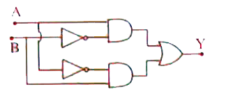
¯¯¯¯¯¯¯¯A.B
A.¯¯¯B+A.¯¯¯B
¯¯¯¯¯¯¯¯¯¯¯A+B
¯¯¯¯¯¯¯¯A.B+A.B
The correct Answer is:B
Topper's Solved these Questions
- SEMICONDUCTOR DEVICESBOOK - AAKASH SERIESCHAPTER - SEMICONDUCTOR DEVICESEXERCISE - EXERCISE - IA
13 Videos
- RAY OPTICSBOOK - AAKASH SERIESCHAPTER - RAY OPTICSEXERCISE - PROBLEMS ( LEVEL-II)
50 Videos
- UNITS AND MEASUREMENTBOOK - AAKASH SERIESCHAPTER - UNITS AND MEASUREMENTEXERCISE - PRACTICE EXERCISE
45 Videos
Similar Questions
Knowledge Check
In the combination of the following gates the output Y can be written in terms of inputs A and B as:
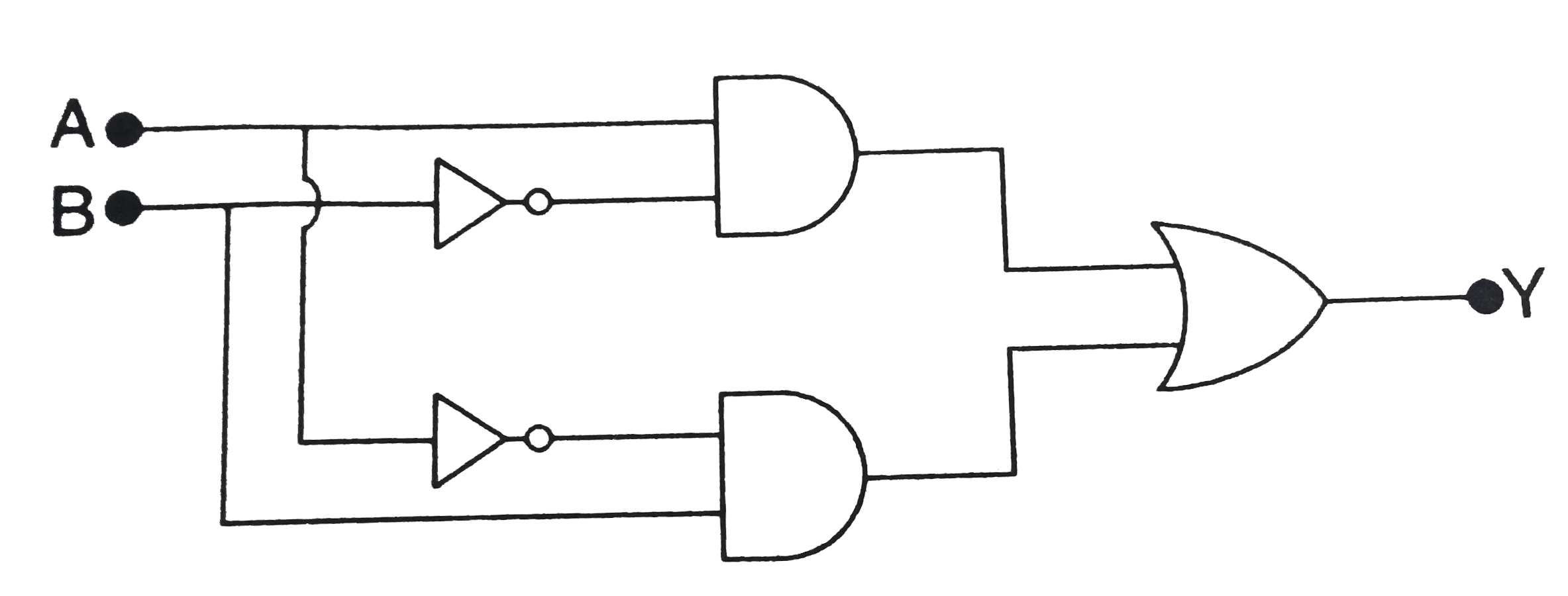 A¯¯¯¯¯¯¯¯A.B+A.BBA.¯¯¯B+¯¯¯A.BC¯¯¯¯¯¯¯¯A.BD¯¯¯¯¯¯¯¯¯¯¯A+B
In AND gate, the output Y is 1 when the inputs A and B are:
AA=1, B=0BA=1, B=1CA=0, B=0DA=0, B=1For the given combination of gates, if the logic states of inputs A,B,C are as follows A=B=C=0 and A=B=1,C=0 then the logic states of output Y are
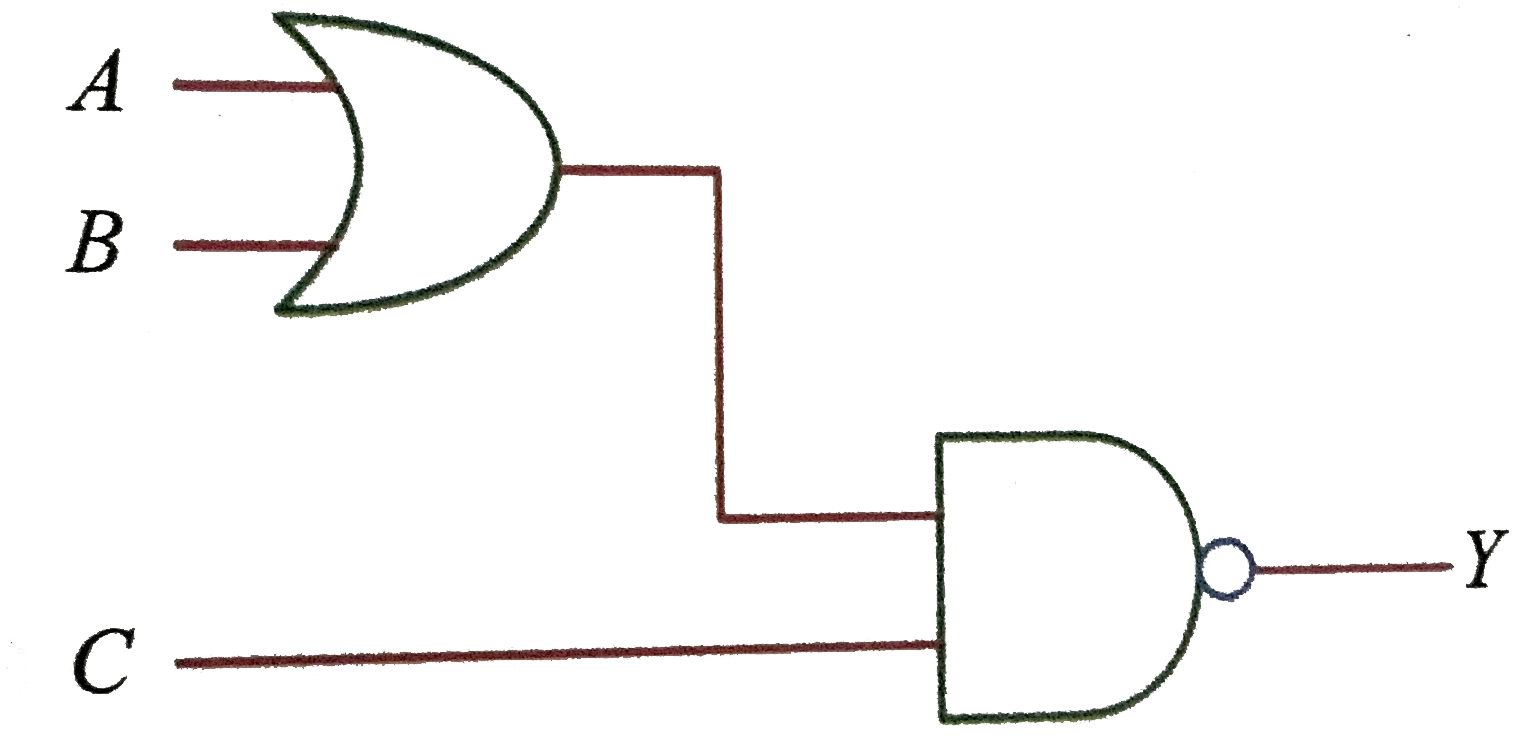 A0,0B0,1C1,0D1,1
The output of a 2-inputs NAND gate is fed to a NOT gate. Write down the truth table for the output of the combination for all possible input of the combination for all possible inputs of A and B.
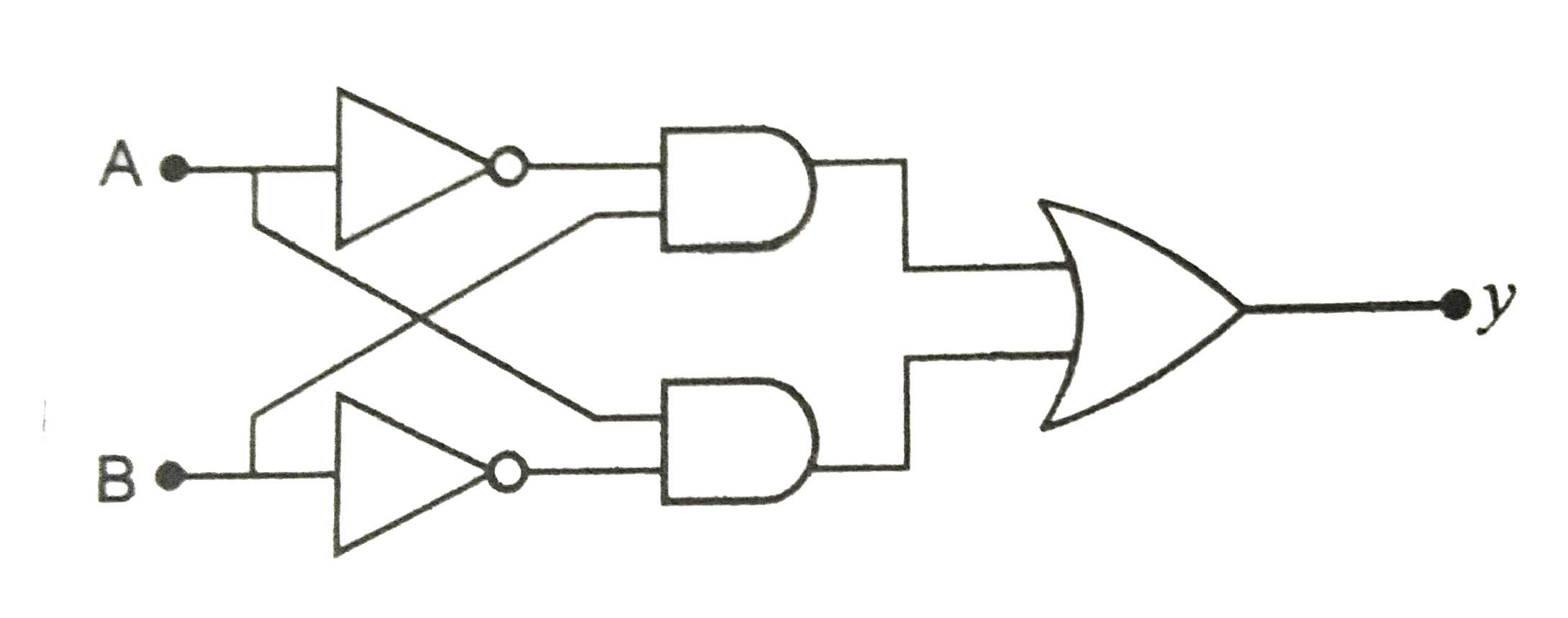
View SolutionFind the Boolean expression of the output y in terms of the input A and B for the circuit shown in Fig.Name the gate formed.
View SolutionFor the given combination of gates, if the logic states of inputs A,B,C, are as follows A=B=C=0 and A=B=1,C=0 then the logic states of output D are
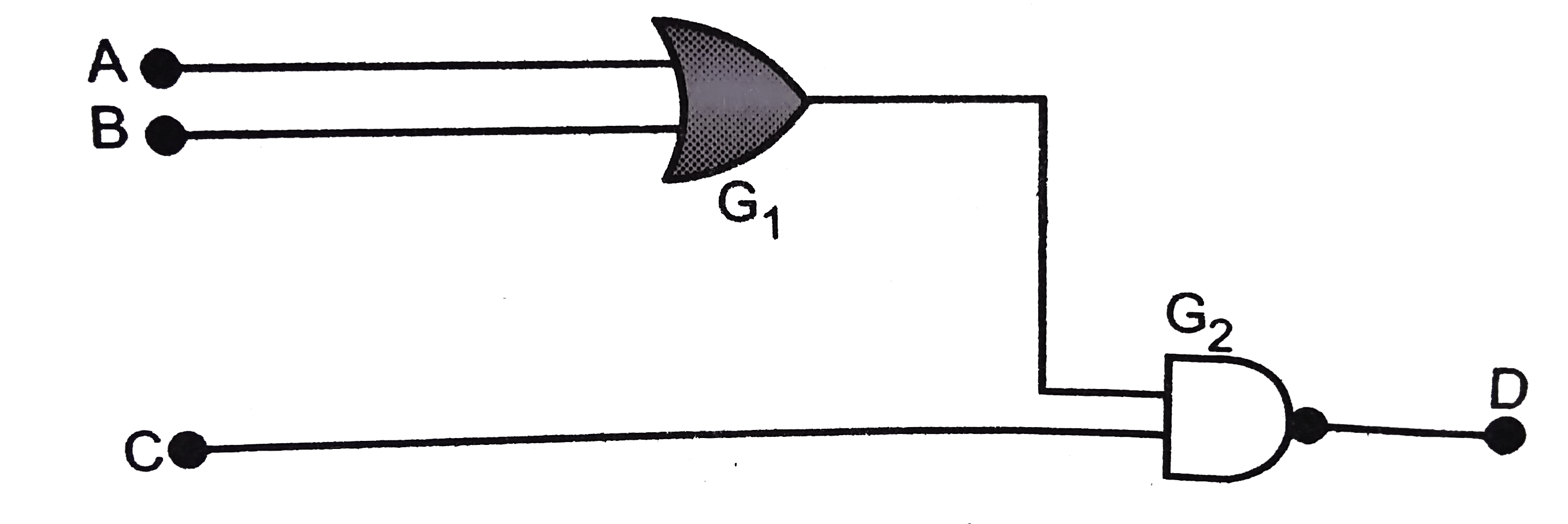
View SolutionFor the given combination of gates, if the logic states of inputs A,B,C are as follows A=B=C=−0 and A=B=1,C=0 then the logic states of output D are

View SolutionFor the given combination of gates, if the logic states of inputs A,B,C, are as follows A=B=C=0 and A=B=1,C=0 then the logic states of output D are

View Solution

