In the given following logic gates input of A & B may be 0 & 1 find output of gate. 
Step by step video & image solution for In the given following logic gates input of A & B may be 0 & 1 find output of gate. by Physics experts to help you in doubts & scoring excellent marks in Class 12 exams.
Topper's Solved these Questions
- BOOK - JEE MAINS PREVIOUS YEARCHAPTER - JEE MAIN 2021EXERCISE - SECTION-A80videos
JEE MAIN 2021
- BOOK - JEE MAINS PREVIOUS YEARCHAPTER - JEE MAIN 2021EXERCISE - SECTION-B40videos
JEE MAIN 2021
- BOOK - JEE MAINS PREVIOUS YEARCHAPTER - JEE MAINEXERCISE - All Questions473videos
JEE MAIN
- BOOK - JEE MAINS PREVIOUS YEARCHAPTER - JEE MAIN 2022EXERCISE - Question492videos
JEE MAIN 2022
Similar Questions
Knowledge Check
- Question 1 - Select One
The following shows a logic gate circuit with two inputs A and B and the output C. The voltage waveforms of A, B and C are as shown below.
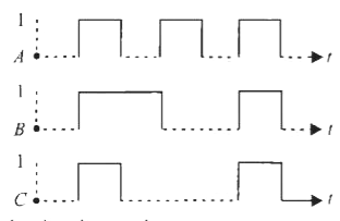
The logic circuit gate isAOR gateBAND gateCNAND gateDNOR gate - Question 2 - Select One
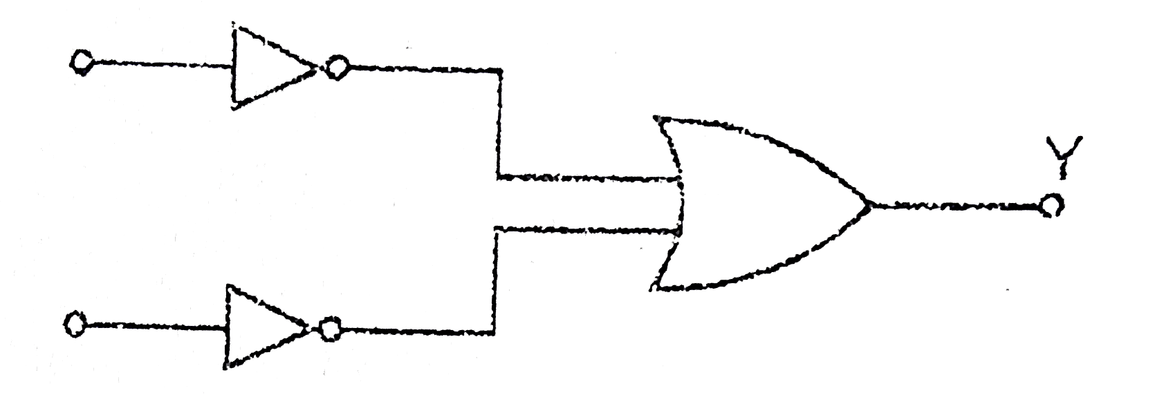
The output Y for the following logic gate circuit will be-AABB¯¯¯A.¯¯¯BC¯¯¯¯¯¯¯¯¯¯¯A+BD¯¯¯¯¯¯¯¯A.B - Question 3 - Select One
In the following combination of logic gates, the outputs of A,B and C are respectively
(i)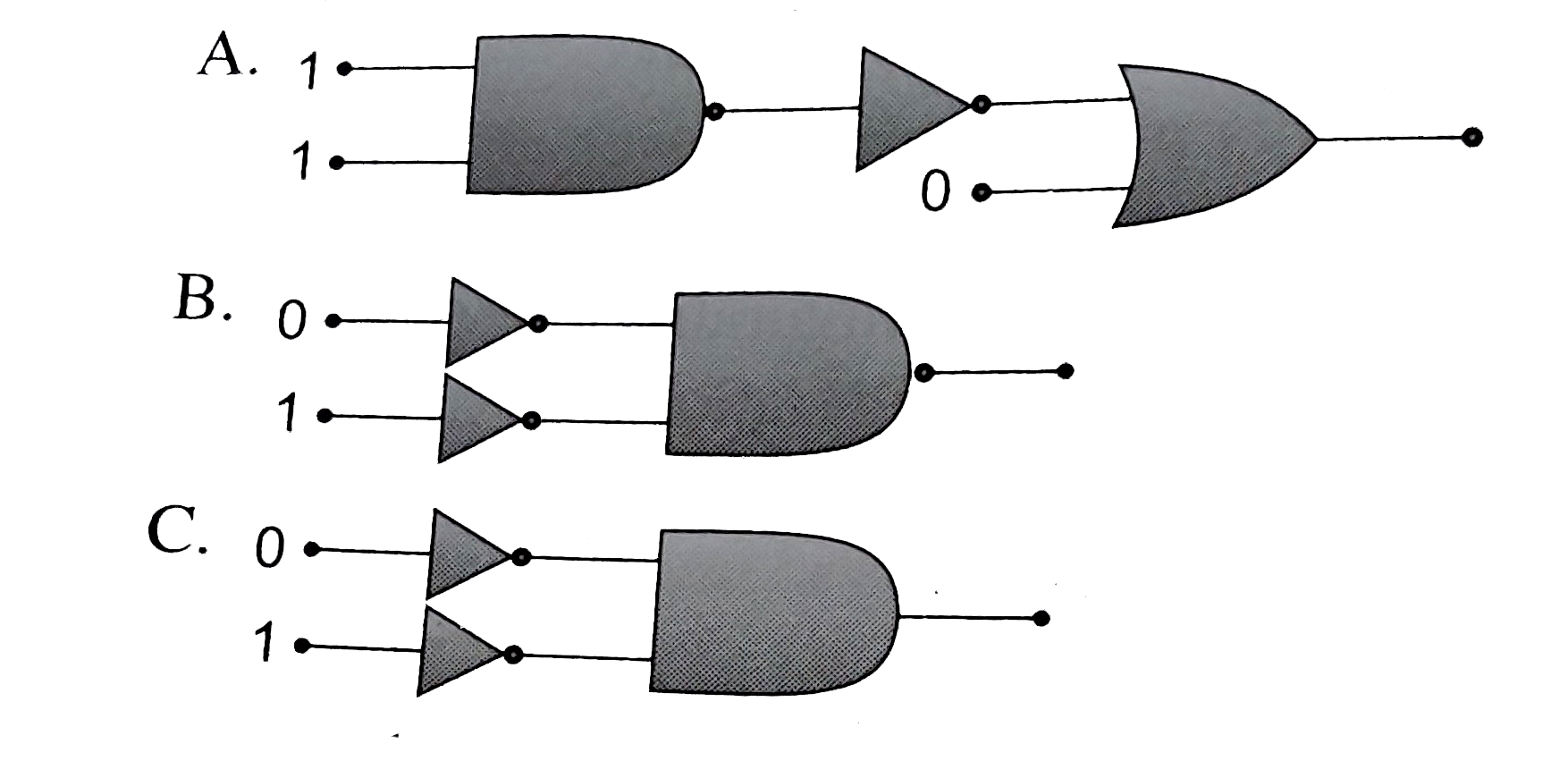 A0,1,1B0,1,0C1,1,0D1,0,1
What is the output X of the following logic gate circuit?
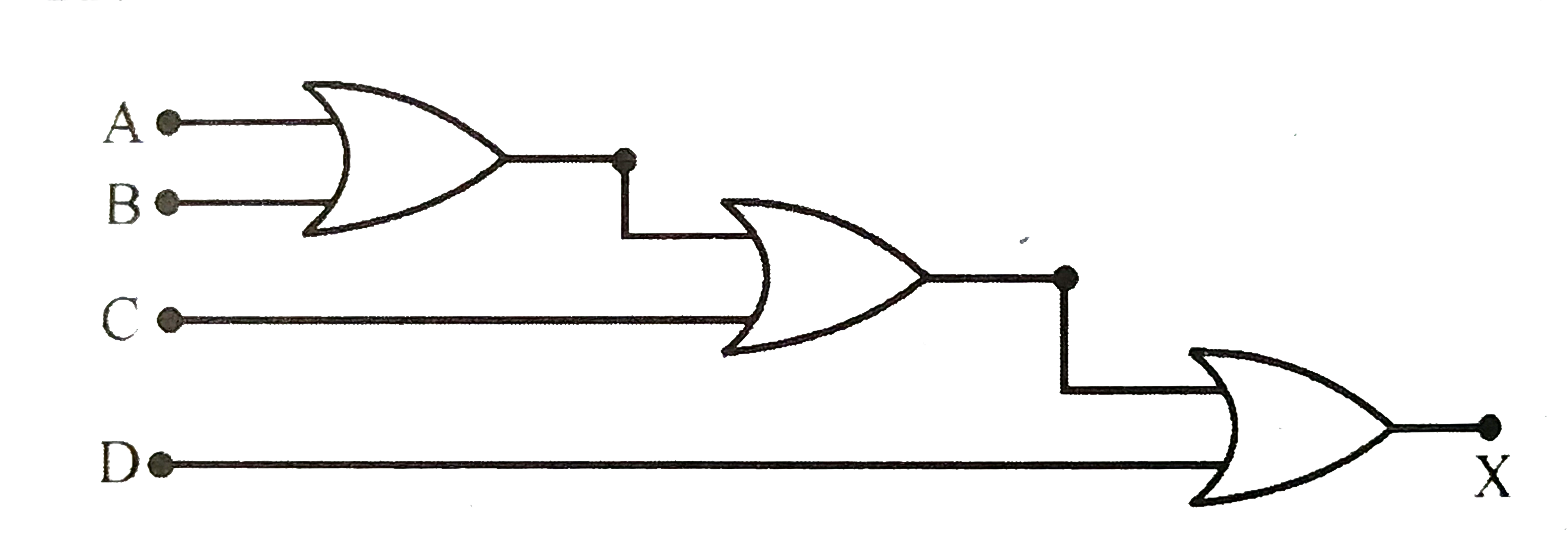 View Solution
An OR gate gives a logic 1 output
View SolutionA NOR gate and a NAND gate are connected shown. Two different sets of inputs are given to this set up. In the first case, the inputs to the gates are A = 0, B = 0, C = 0. In the second case, the inputs are A = 1, B = 0, C = 1. The output D in the first case and second case respectively are
 View Solution
The logic gate having an output of 1 is.
(i)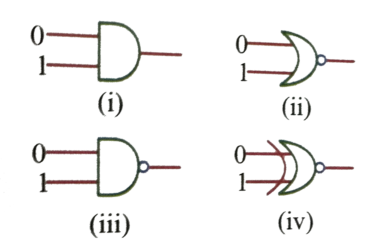 View Solution
The following figure shows a logic gate circuit with two inputs A and B output C. The voltage waveforms of A,B and C are as shown in second figure given below :-
_E01_436_Q01.png)
The logic circuit gate is :-View Solution


