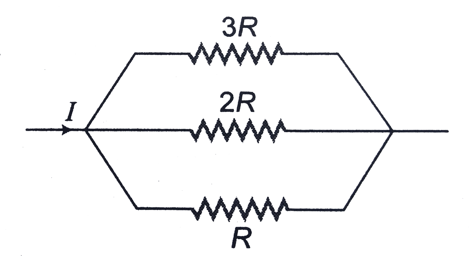
Assertion: In the part of the circuit shown in figure, maximum power is produced across R.
Reason : Power P=V2R
If both Assertion and Reason are true and the Reason is correct explanation of the Assertion.
If both Assertion and Reason are true but Reason is not the correct explanation of Assertion.
If Assertion is true, but the Reason is false.
If Assertion is false but the Reason is true.
The correct Answer is:A, B
In parallel, V=constant
∴ From the equation
P=V2R⇒P∝1R
Topper's Solved these Questions
- CURRENT ELECTRICITYBOOK - DC PANDEY ENGLISHCHAPTER - CURRENT ELECTRICITYEXERCISE - Level 1 Objective
40 Videos
- CURRENT ELECTRICITYBOOK - DC PANDEY ENGLISHCHAPTER - CURRENT ELECTRICITYEXERCISE - OBJECTIVE_TYPE
1 Videos
- CURRENT ELECTRICITYBOOK - DC PANDEY ENGLISHCHAPTER - CURRENT ELECTRICITYEXERCISE - Exercise 23.13
2 Videos
- COMMUNICATION SYSTEMBOOK - DC PANDEY ENGLISHCHAPTER - COMMUNICATION SYSTEMEXERCISE - Subjective
11 Videos
- ELECTROMAGNETIC INDUCTIONBOOK - DC PANDEY ENGLISHCHAPTER - ELECTROMAGNETIC INDUCTIONEXERCISE - Medical entrances gallery
25 Videos
Similar Questions
Knowledge Check
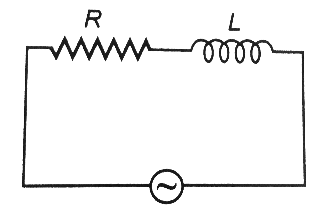
The power factor of the circuit as shown in figure is
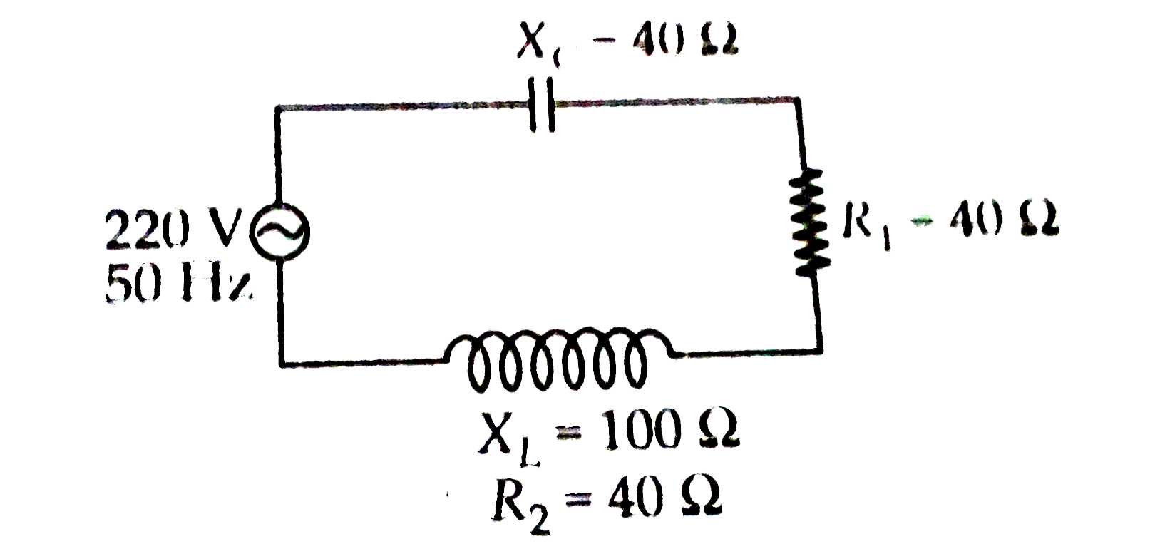 A0.2B0.4C0.8D0.6
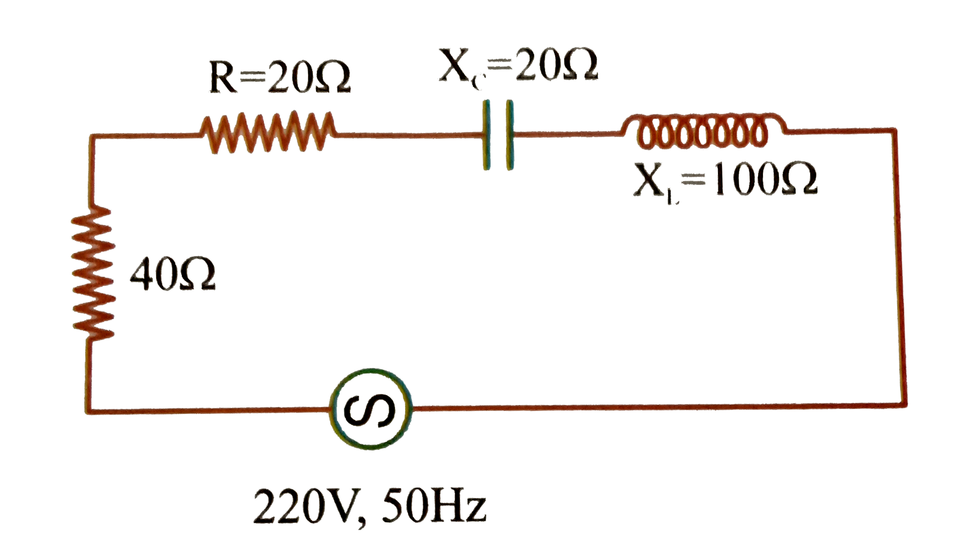
In the circuit shown in figure, the power consumed is
 .
.
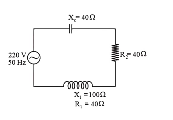
View SolutionThe power factor of the circuit shown in the figure is
View SolutionCalculate the power factor of the circuit shown in figure
View SolutionIn the circuit shown in figure resistance of each wire is r. Net resistance across

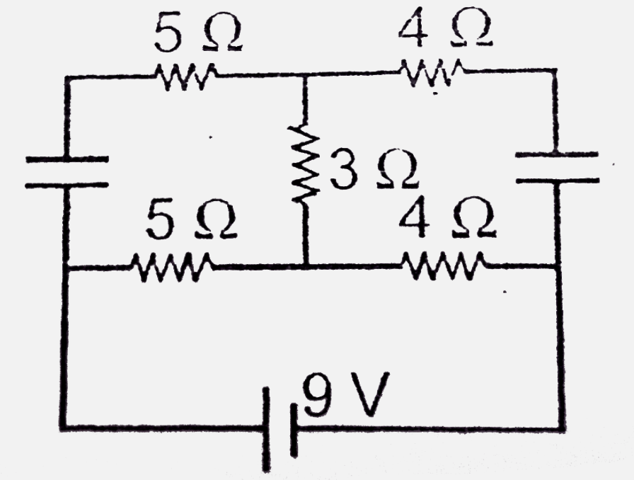
View SolutionThe power consumption by the circuit shown in figure at steady state is
View SolutionAssertion: In the circuit shown in figure no charge will stored in the capacitor.
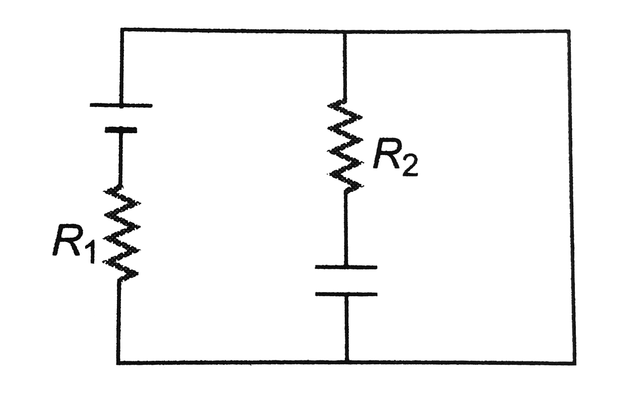
Reason: Current through R2 will be zero.
View Solution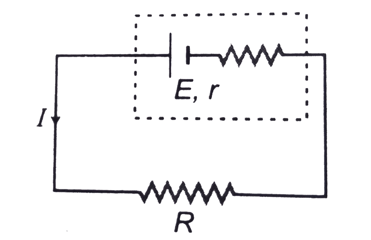
Assertion :In the circuit shown in figure R is variable. Value of current I is maximum when R=r.
Reason: At R=r, maximum power is produced across R.
View Solution

