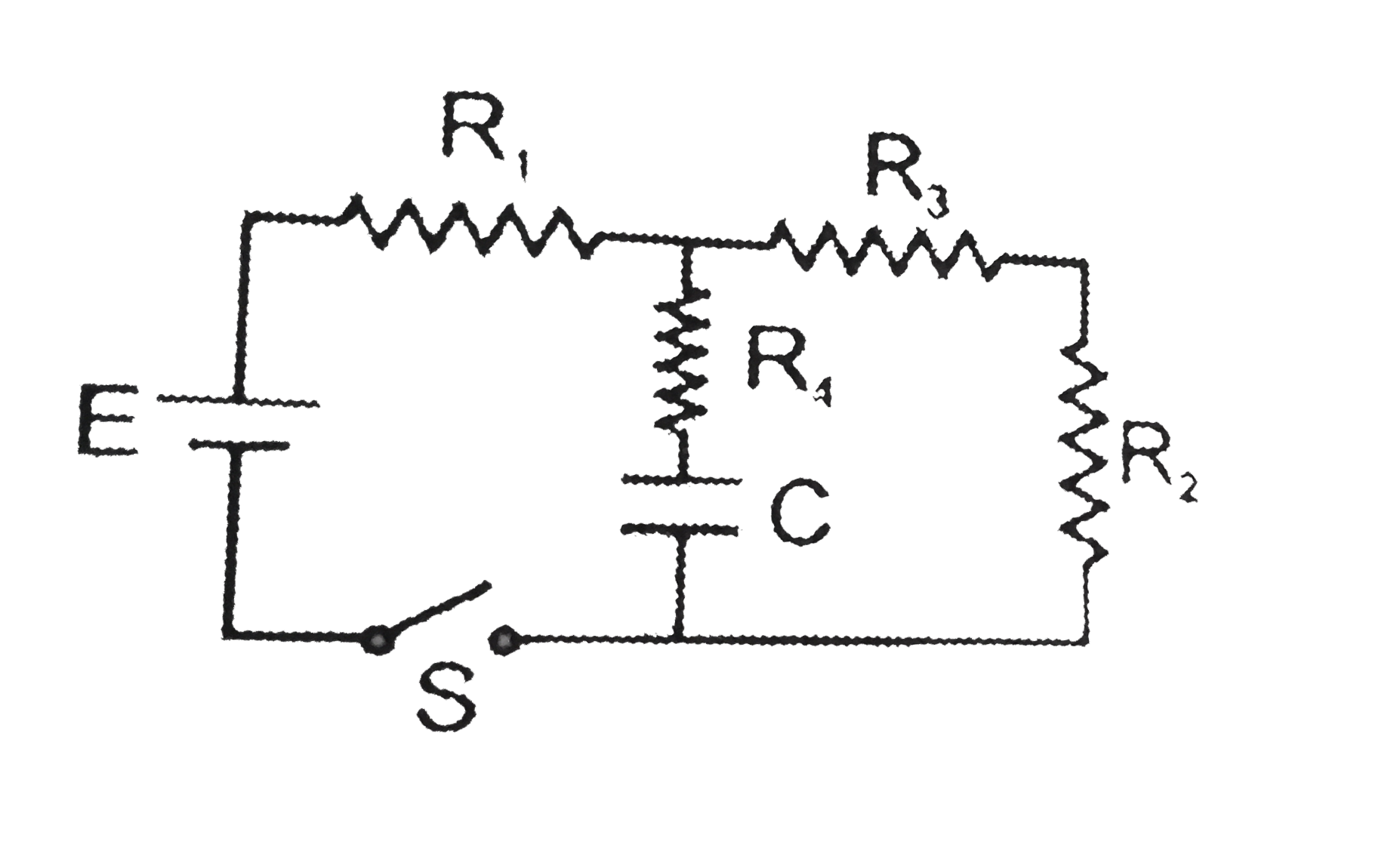
Switch S is closed at time t=0. in the circuit shown in figure. 
a. Find the time varying quantities in the circuit.
b. Find the their values at time t=0
c. Find their vales at time t=∞
Find the time constant of all time varying function
e. Make their exponetial graphs and write their exponential equations.
f. just write the equations to slove them to find different time varying functions.
Text Solution
a. 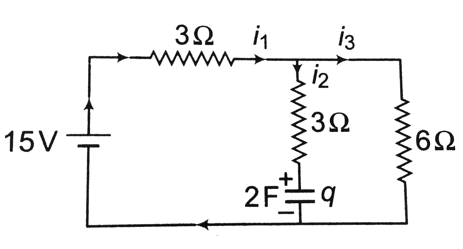
There are four times variable functions i1,i2 and q.
b.At t=0 equivalent resistance of capacitor is zero. So, the simple circuit is as shown below
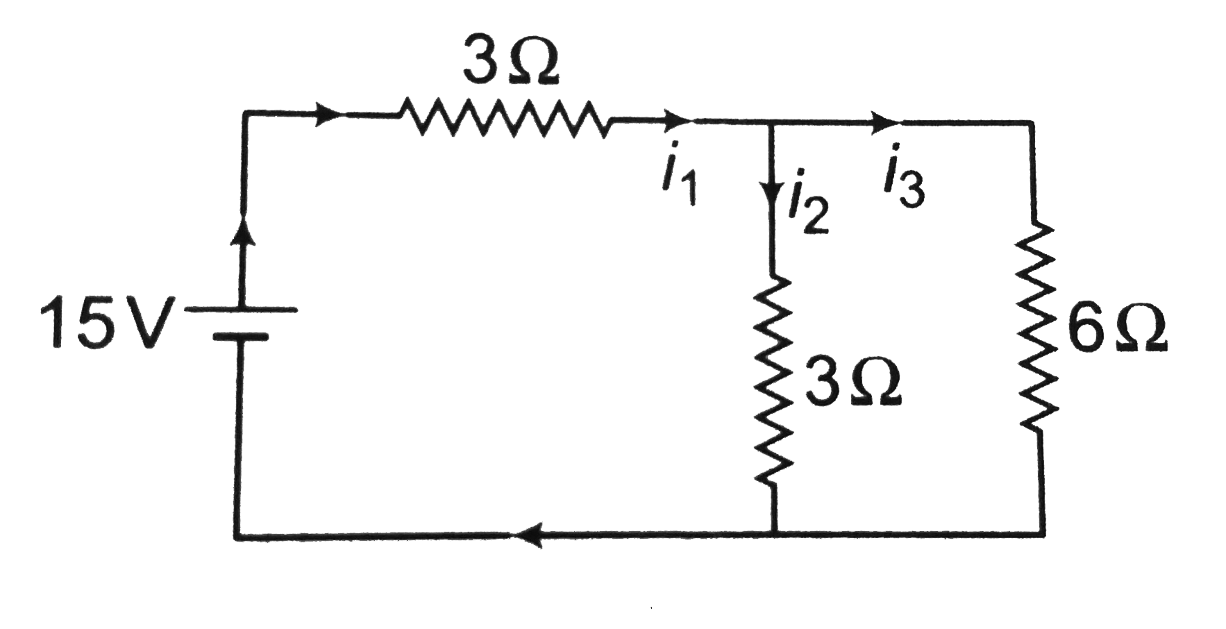
Rnet=3+3×63=6=5Ω
i1=155=3A⇒i2i3=63=21
∴i2=22+1(3A)=2A
i3=(12+1)(3A)=1A and q=0
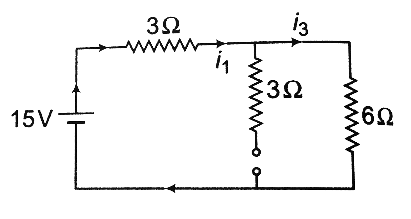
c. t=∞ equilavent resistance of capacitor is infinite.So, equivalent circuit is as shown below i1=i3=153+6=53A
i2=0
V2F=V6Ω=iR=(53)(6)=10volt
q=CV=(2)(10)=20C
d.By short circuiting the battery the simplified circuit is as shown below
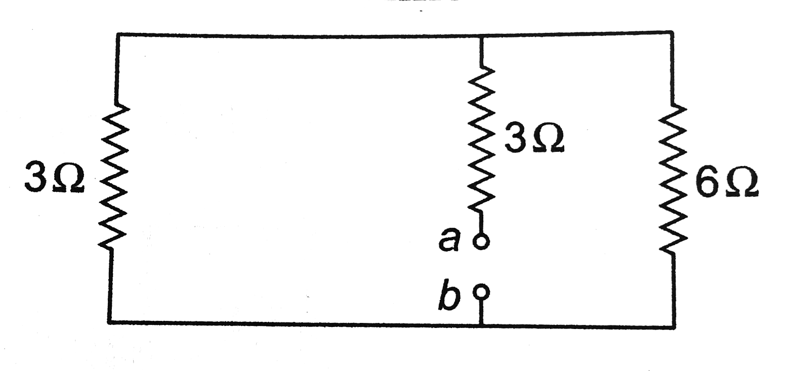
Net resistance across capacitor or ab is
Rnet=3+3×63+6=5Ω
∴τC=CR≠t=(2)(5)=10s
e. Exponential graphs and their exponential equations are as under.

i1=53+(3−53)e−teτc
i2=2e−tτC=2e−t10
i3=1+(53−1)(1−e−t(τC))=1+23(1−e−t10) ltbr gt q=20(1−e−tτC)=20(1−e−t10)
f. Unknowns are four i1,i2,i3 and q . So corresponding to the figure of part a four equations are
i1=i2+i3............i
i2=dqdt..........ii
Applying loop equation in left hand side loop.
+15−3i1−3i2−q2=0 ..............iii
Applying loop equation in right hand side loop,
+q2+3i2−6i3=0 ..............iv.
Soving these equations (with some integration), we can find same time function as we have obtained in part e.
|
Topper's Solved these Questions
- CAPACITORSBOOK - DC PANDEY ENGLISHCHAPTER - CAPACITORSEXERCISE - Exercise
155 Videos
- CAPACITORSBOOK - DC PANDEY ENGLISHCHAPTER - CAPACITORSEXERCISE - OBJECTIVE_TYPE
1 Videos
- ATOMSBOOK - DC PANDEY ENGLISHCHAPTER - ATOMSEXERCISE - MEDICAL ENTRANCES GALLERY
42 Videos
- COMMUNICATION SYSTEMBOOK - DC PANDEY ENGLISHCHAPTER - COMMUNICATION SYSTEMEXERCISE - Subjective
11 Videos
Similar Questions
Knowledge Check
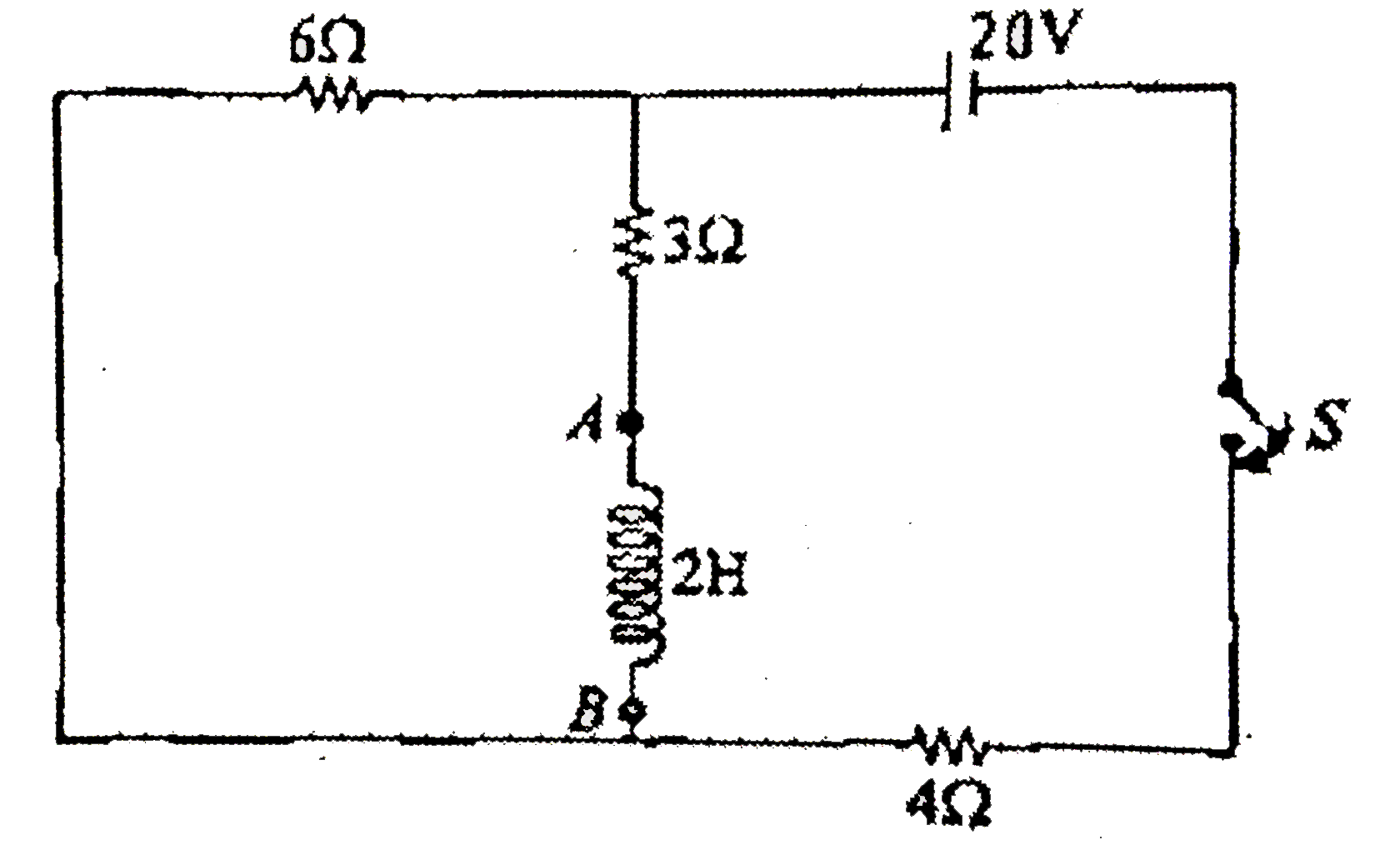
In the circuit shown in figure switch S is closed at time t=0, which statement is true after one time constant of L-R circuit?
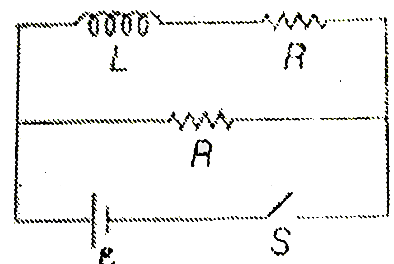 Acharge passes through inductor 2LεR(1−e−1)Bcurrent through battery ε2R(1−e−1)Ccharge passes through inductor LεR2(e−1)DCurrent through battery is 2εR
In the circuit shown in figure, circuit is closed at time t=0. At time t=ln(2) second
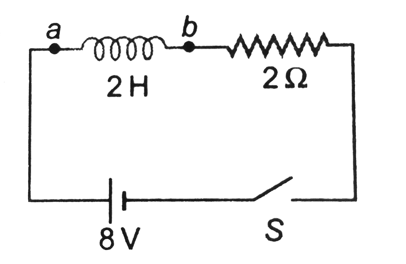 Arate of energy supplied by the battery is 16 J/sBrate of heat dissipated across resistance is 8J/sCrate of heat dissipated across resistance is 16 J/sDVa−Vb=4V
In the circuit shown in figure switch S is closed at time t=0. The charge which passes through the battery in one time constant is
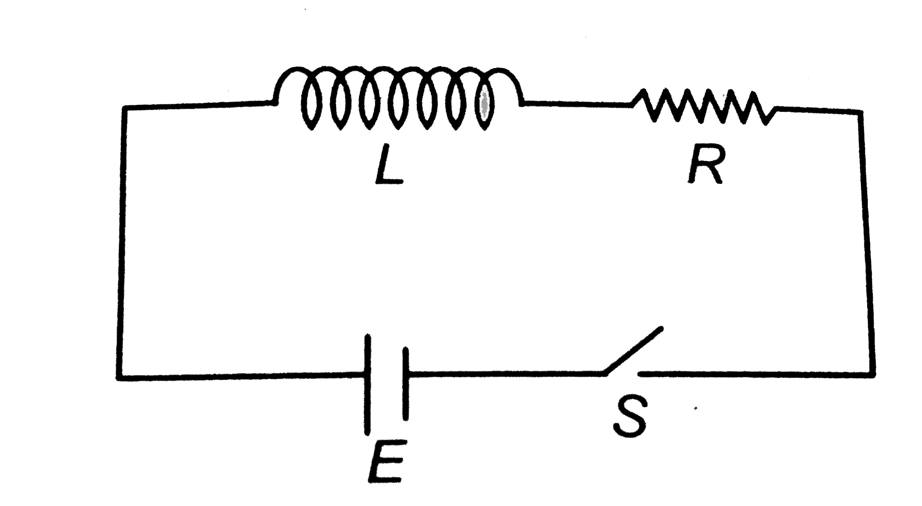 AeR2ELBE(LR)CELeR2DeLER
In the circuit shown in figure, circuit is closed at time t=0. At time t=ln(2) second

View SolutionIn the circuit shown in figure the switch S is closed at t = 0. A long time after closing the switch
View SolutionIn the circuit shown in figure switch S is closed at time t=0. The charge which passes through the battery in one time constant is

View Solution
In given LR circuit the switch S is closed at time t=0 then
View Solution
In given LR circuit the switch S is closed at time t=0 then
View Solution

