Give Boolean expression and Truth table for NOR gate.
C=A+B
C=¯¯¯¯¯¯¯¯¯¯¯A+B
C=A.B
C=¯¯¯¯¯¯¯¯A.B
The correct Answer is:B
To solve the question regarding the Boolean expression and truth table for a NOR gate, we can follow these steps:
Step 1: Understand the NOR Gate
The NOR gate is a digital logic gate that outputs true or 1 only when both of its inputs are false or 0. It is essentially a combination of an OR gate followed by a NOT gate.
Step 2: Write the Boolean Expression
For a NOR gate with two inputs A and B, the output C can be expressed in Boolean algebra. The OR operation is represented by the plus sign (+), and the NOT operation is represented by a complement ('). Therefore, the Boolean expression for the NOR gate is:
C=(A+B)′
This means that the output C is the complement of the logical sum of A and B.
Step 3: Identify the Correct Option
From the given options:
1. C=A+B
2. C=(A+B)′ (This is the correct option)
3. C=A⋅B
4. C=(A⋅B)′
The correct Boolean expression for the NOR gate is option 2: C=(A+B)′.
Step 4: Create the Truth Table
Now, we will create the truth table for the NOR gate. The truth table lists all possible combinations of inputs A and B and the corresponding output C.
| A | B | A + B | C = (A + B)' |
|---|---|-------|--------------|
| 0 | 0 | 0 | 1 |
| 0 | 1 | 1 | 0 |
| 1 | 0 | 1 | 0 |
| 1 | 1 | 1 | 0 |
Explanation of the Truth Table:
- When both A and B are 0, A+B=0 and C=(0)′=1.
- When A is 0 and B is 1, A+B=1 and C=(1)′=0.
- When A is 1 and B is 0, A+B=1 and C=(1)′=0.
- When both A and B are 1, A+B=1 and C=(1)′=0.
Final Answer
- Boolean Expression: C=(A+B)′
- Truth Table:
| A | B | C |
|---|---|---|
| 0 | 0 | 1 |
| 0 | 1 | 0 |
| 1 | 0 | 0 |
| 1 | 1 | 0 |
The NOR gate is a digital logic gate that outputs true or 1 only when both of its inputs are false or 0. It is essentially a combination of an OR gate followed by a NOT gate.
For a NOR gate with two inputs A and B, the output C can be expressed in Boolean algebra. The OR operation is represented by the plus sign (+), and the NOT operation is represented by a complement ('). Therefore, the Boolean expression for the NOR gate is:
C=(A+B)′
This means that the output C is the complement of the logical sum of A and B.
From the given options:
1. C=A+B
2. C=(A+B)′ (This is the correct option)
3. C=A⋅B
4. C=(A⋅B)′
Now, we will create the truth table for the NOR gate. The truth table lists all possible combinations of inputs A and B and the corresponding output C.
|---|---|-------|--------------|
| 0 | 0 | 0 | 1 |
| 0 | 1 | 1 | 0 |
| 1 | 0 | 1 | 0 |
| 1 | 1 | 1 | 0 |
- When both A and B are 0, A+B=0 and C=(0)′=1.
- When A is 0 and B is 1, A+B=1 and C=(1)′=0.
- When A is 1 and B is 0, A+B=1 and C=(1)′=0.
- When both A and B are 1, A+B=1 and C=(1)′=0.
- Boolean Expression: C=(A+B)′
- Truth Table:
| A | B | C |
|---|---|---|
| 0 | 0 | 1 |
| 0 | 1 | 0 |
| 1 | 0 | 0 |
| 1 | 1 | 0 |
Topper's Solved these Questions
- SEMICONDUCTORS AND ELECTRONIC DEVICESBOOK - DC PANDEY ENGLISHCHAPTER - SEMICONDUCTORS AND ELECTRONIC DEVICESEXERCISE - More than One Option is Correct
3 Videos
- ROTATIONAL MOTIONBOOK - DC PANDEY ENGLISHCHAPTER - ROTATIONAL MOTIONEXERCISE - Integer Type Questions
17 Videos
- SIMPLE HARMONIC MOTIONBOOK - DC PANDEY ENGLISHCHAPTER - SIMPLE HARMONIC MOTIONEXERCISE - Integer type questions
14 Videos
Similar Questions
Knowledge Check
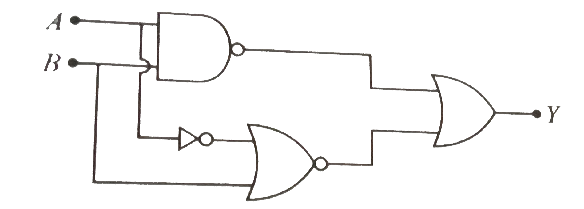
The Boolean expression for the given circuit is
 A¯¯¯¯¯¯¯¯A.BBA+BC¯¯¯A+BDA+¯¯¯B
Assertion:

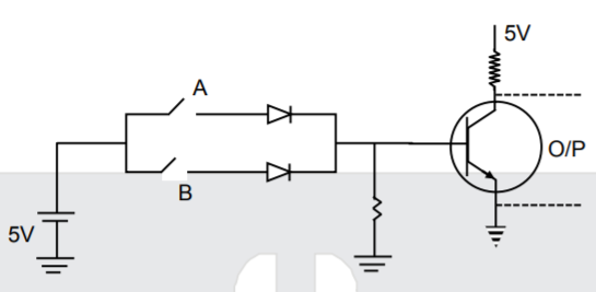
This circuit acts as OR Gate.
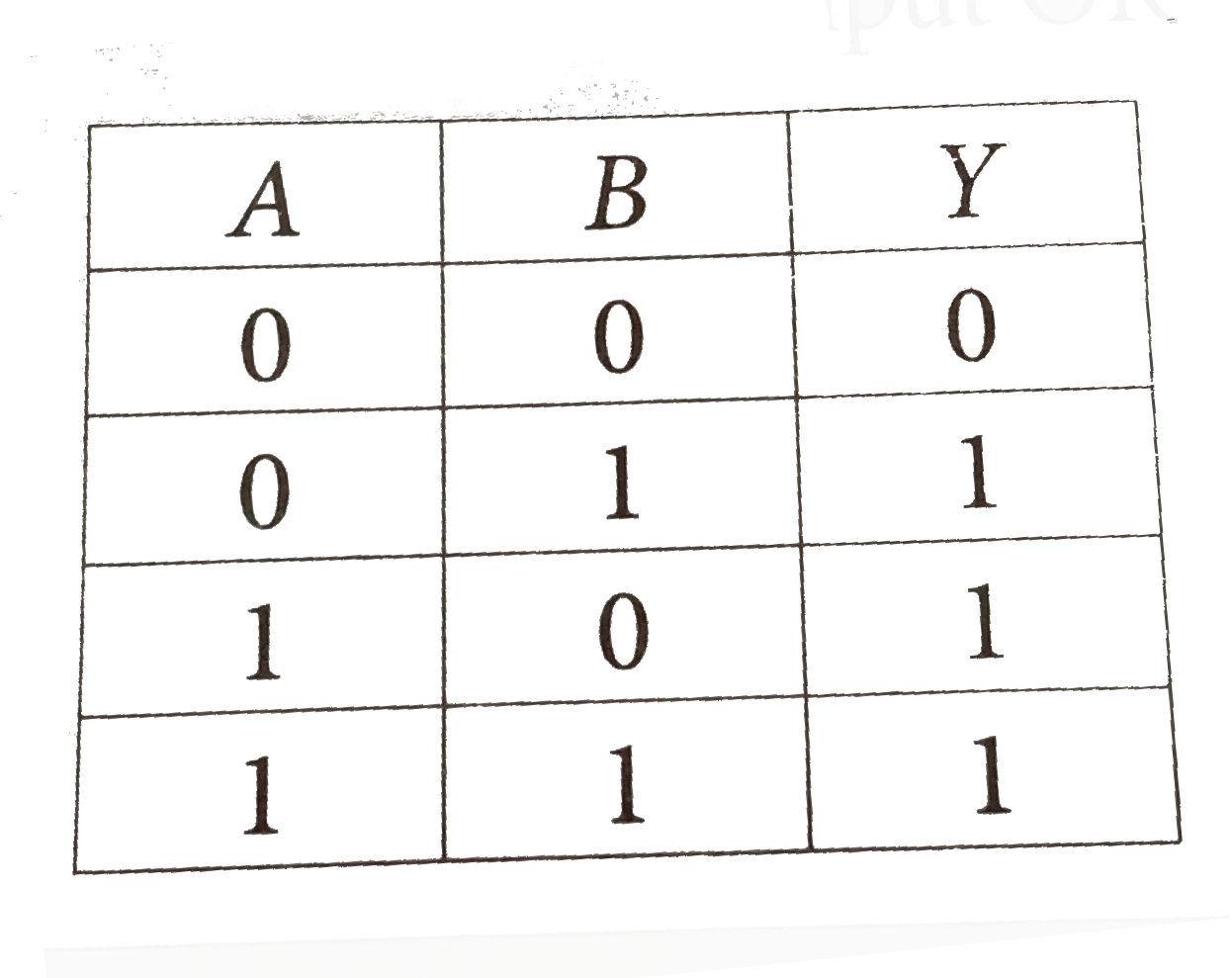
Reason: Truth table for two input OR Gate is AIf both assertion and reason are true and reason is the correct explanation of assertion.BIf both assertion and reason are true not but reason is not the correct explanation of assertion.CIf assertion is true but reason is falseDIf both assertion and reason are false.
The Boolean expression of the output y in terms of the input A and B for the circuit shown in figure.
 A¯¯¯AB+A¯¯¯BBABCAB+¯¯¯A¯¯¯BDA¯¯¯B+1
Which one of the following Boolean expressions is a tautology?
View SolutionGive the truth table and circuit symbol for NAND gate.
View SolutionChoose the correct Boolean expression for the given circuit diagram:

View Solution
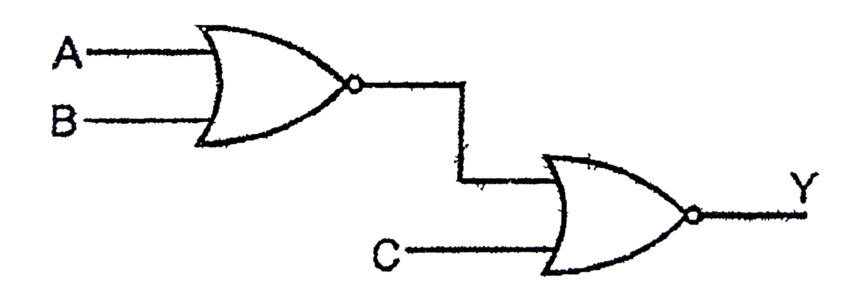
The Boolean expression for the output Y of the logic operation shown is-
View SolutionName the gate , which represents the Boolean expression y = A. B for inputs A, B
View Solution
