The series and parallel circuits shown in figure have the same impedance and the same power factor. If R=3ΩandX=4Ω, find the values of R1andX1. Also, find the impedance and power factor.
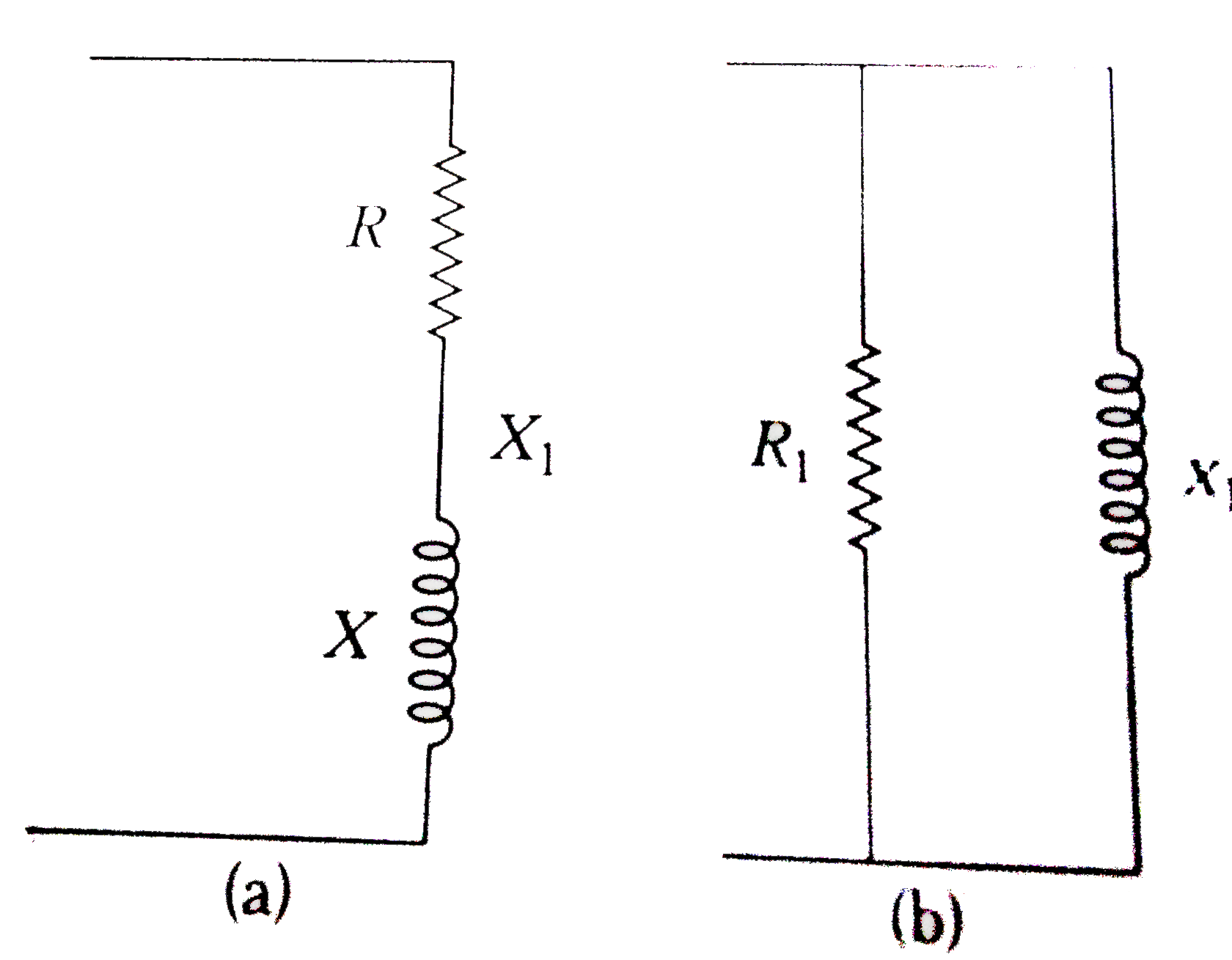
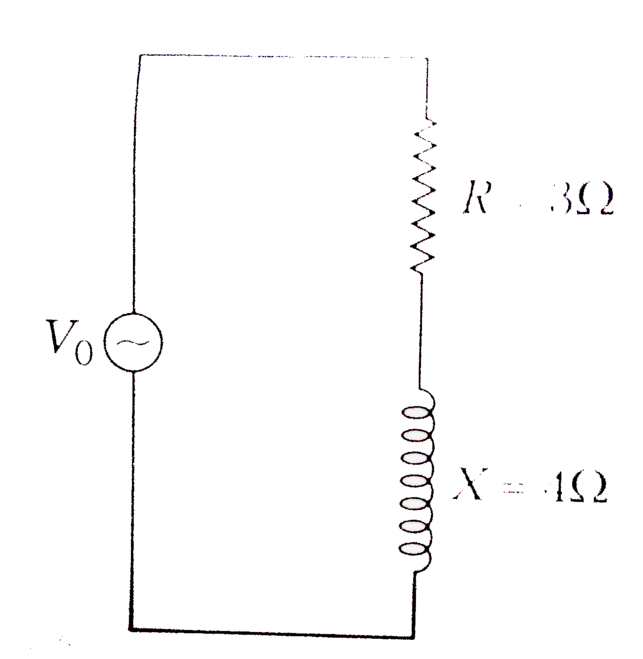
Impedance, Z=√R2+X2=5Ω
Power factor, cosϕ=RZ=35⇒ϕ=cos−1(0,6)
⇒tanϕ=XR=43
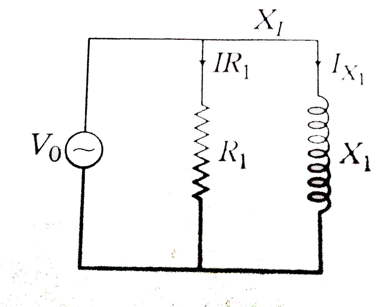
Now, we have, (IR)L=V0R1,(IX1)0=V0X1
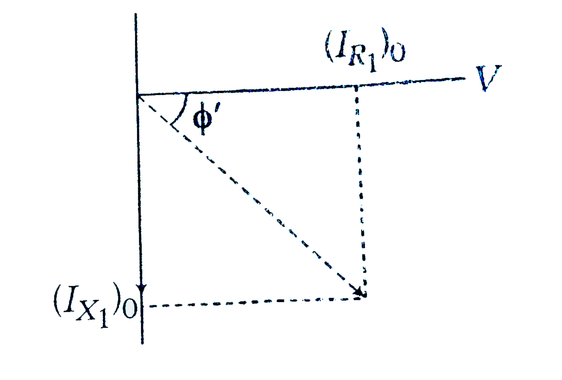
I0=⎛⎝√(IR1)2+(IX1)20=√(V0R1)2+(V0X1)2
⇒V0Z=V0√1R21+1X21⇒Z=1√1R21+1X21=5
tanϕ′=(IXL)0(IR1)0=V0/X1V0/R1=R1X1=tanϕ=43
Putting X1=34R1 in Eq. (i)
⇒1R2+1(34R1)2=152
⇒1R21(1+169)=125=1R2=9(25)2
⇒R1=253Ω
⇒X1=34R1=254Ω
Similar Questions
The power dissipated in the circuit shown in the figure is 30 W. The value of R is
View SolutionIn the circuit shown in figure
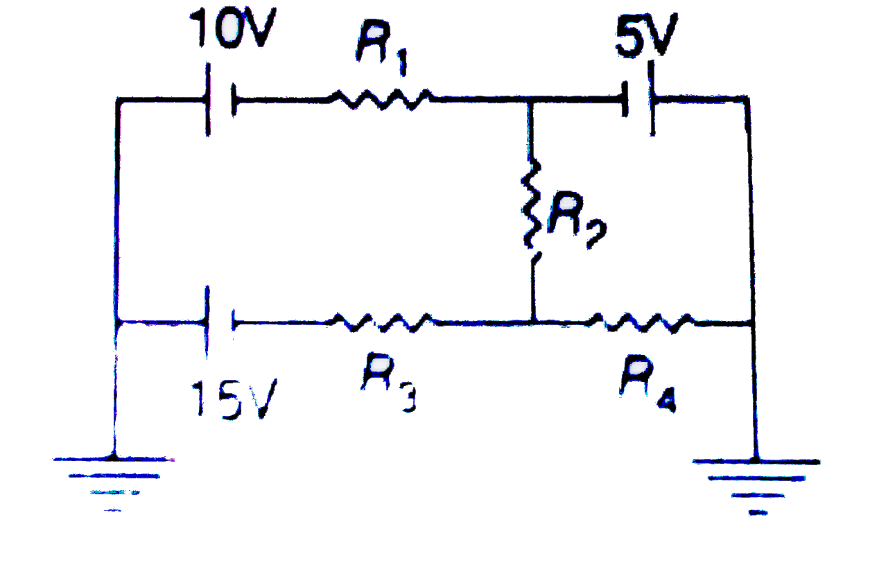
Current through R2 is zero if R4=2Ω and R3=4Ω In this case
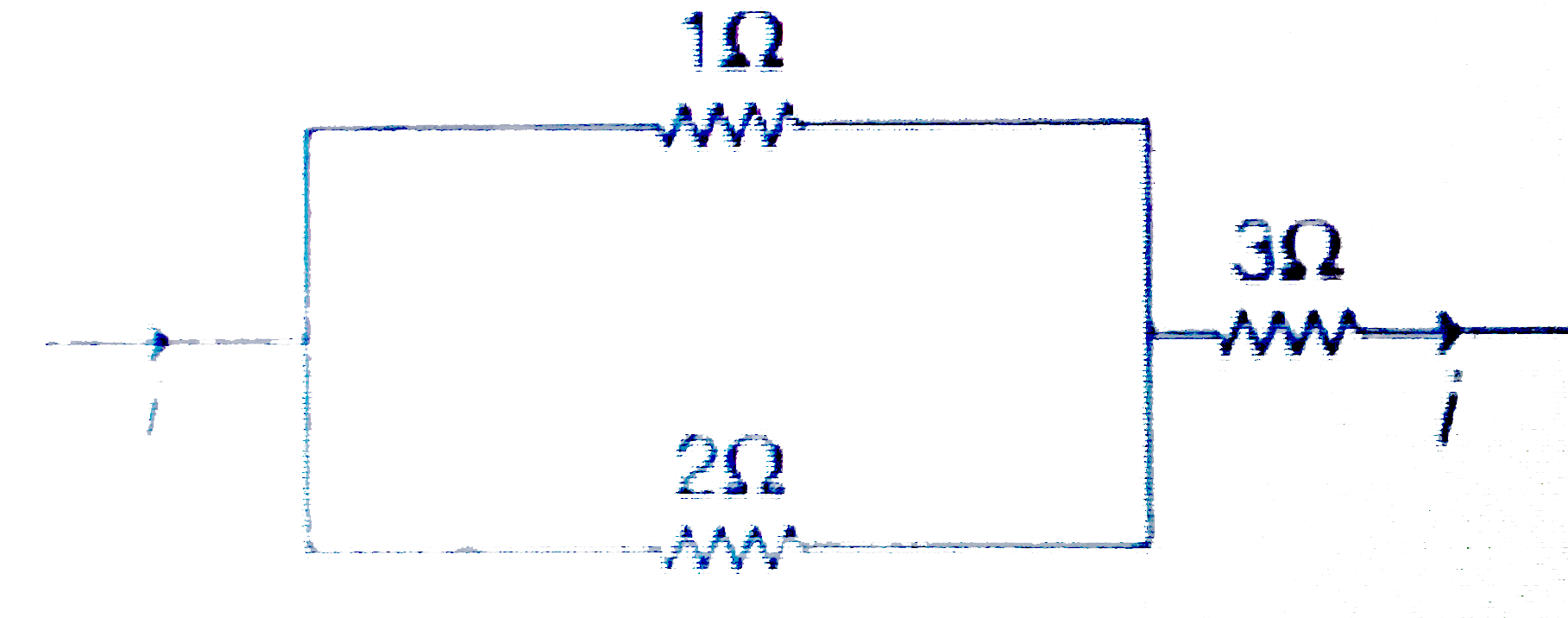
View SolutionIn the circuit shown in figure, power developed across 1Ω,2Ω and 3Ω resistance are in the ratio of
View SolutionThe impedance of a circuit consister of 3Ωresistance and 4Ω reactance. The power factor of the circuit is
View SolutionThe impedance of a series circuit consists of 3ohm resistance and 4ohm reactance.The power factor of the circuit is
View SolutionIn a series LCR circuit, the total reactance is 4Ω and resistance is 3Ω . Its power factor is
View SolutionAC voltage source (V,ω) is applied across a parallel LC circuit as shown in figure. Find the impedance of the circuit and phase of current.

View SolutionIn the given circuit, power factor between A and B is 0.5 and over all power factor of the circuit is 1.
Find the value of Rand L
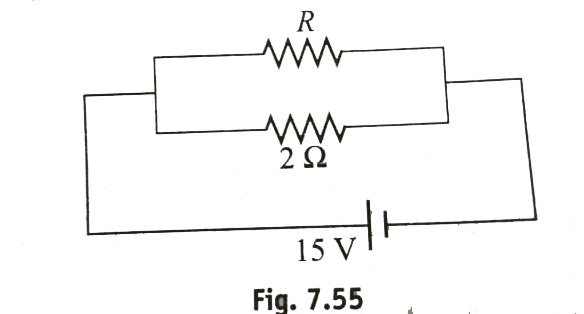
View SolutionIf in the circuit shown in Fig.7.55, power dissipation is 150W , then find the value of R(inΩ).
View SolutionIn the network shown in the figure, power dissipated in 3Ω and 12 W. Power dissipated in 4Ω will be

View Solution
