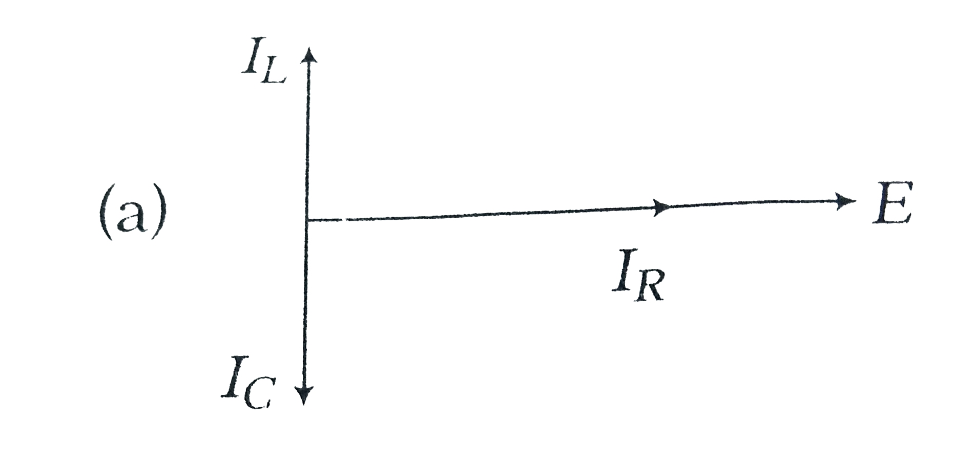
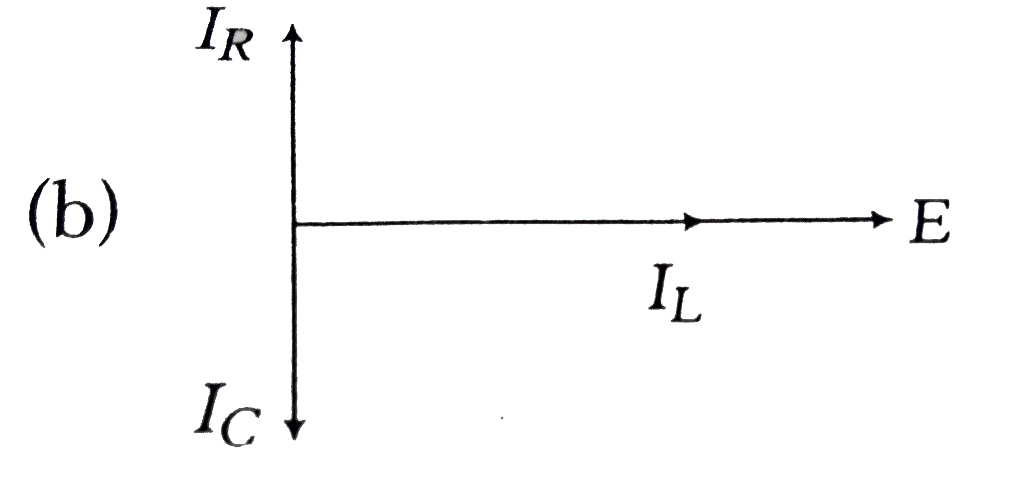
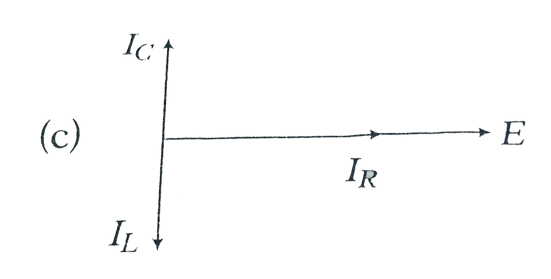
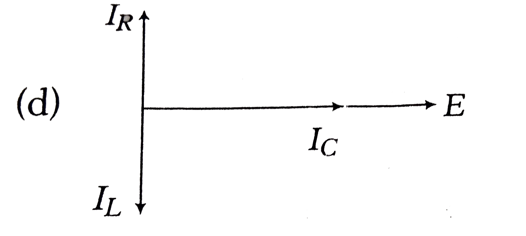
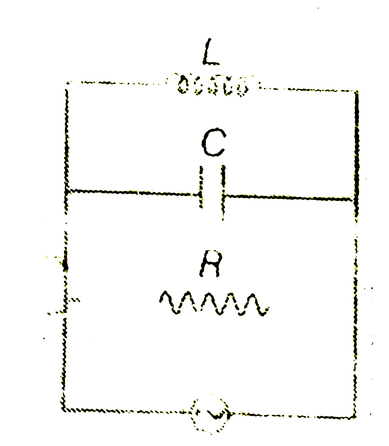
An alternating emf is applied across a parallel combination of a resistance R, capacitance C and an inductance L. If IR, IL and IC are the currents through R,L and C respectively, the phase relationship among IR, IL and IC and source emf E, is given by
The correct Answer is:C
To solve the problem of the phase relationship among the currents through the resistor (IR), inductor (IL), and capacitor (IC) in a parallel AC circuit, we can follow these steps:
1. Understand the Circuit Configuration:
- We have a parallel combination of a resistor (R), inductor (L), and capacitor (C) connected to an alternating EMF (E).
- In a parallel circuit, the voltage across all components is the same, which is equal to the source EMF (E).
2. Identify the Current Relationships:
- The current through the resistor (IR) is in phase with the EMF (E). This means that the phasor for IR is aligned with the phasor for E.
- The current through the capacitor (IC) leads the voltage across it (E) by 90 degrees (or π/2 radians).
- The current through the inductor (IL) lags the voltage across it (E) by 90 degrees (or π/2 radians).
3. Draw the Phasor Diagram:
- Start by drawing the phasor for the EMF (E) along the horizontal axis (real axis).
- Draw the phasor for the current through the resistor (IR) along the same direction as E since they are in phase.
- Draw the phasor for the current through the capacitor (IC) vertically upwards (positive y-axis) because it leads the EMF by π/2.
- Draw the phasor for the current through the inductor (IL) vertically downwards (negative y-axis) because it lags the EMF by π/2.
4. Analyze the Phasor Relationships:
- From the phasor diagram, we can see that:
- IR is along the same direction as E.
- IC is along the positive y-axis.
- IL is along the negative y-axis.
- This indicates the phase relationships:
- IR (in phase with E)
- IC (leads E by π/2)
- IL (lags E by π/2)
5. Select the Correct Option:
- Based on the analysis and the phasor diagram, we can conclude that the correct option representing the phase relationship among IR, IL, IC, and E is the one that matches our findings.
Final Answer:
The correct option for the phase relationship among IR, IL, IC, and the source EMF E is Option C.
- We have a parallel combination of a resistor (R), inductor (L), and capacitor (C) connected to an alternating EMF (E).
- In a parallel circuit, the voltage across all components is the same, which is equal to the source EMF (E).
- The current through the resistor (IR) is in phase with the EMF (E). This means that the phasor for IR is aligned with the phasor for E.
- The current through the capacitor (IC) leads the voltage across it (E) by 90 degrees (or π/2 radians).
- The current through the inductor (IL) lags the voltage across it (E) by 90 degrees (or π/2 radians).
- Start by drawing the phasor for the EMF (E) along the horizontal axis (real axis).
- Draw the phasor for the current through the resistor (IR) along the same direction as E since they are in phase.
- Draw the phasor for the current through the capacitor (IC) vertically upwards (positive y-axis) because it leads the EMF by π/2.
- Draw the phasor for the current through the inductor (IL) vertically downwards (negative y-axis) because it lags the EMF by π/2.
- From the phasor diagram, we can see that:
- IR is along the same direction as E.
- IC is along the positive y-axis.
- IL is along the negative y-axis.
- This indicates the phase relationships:
- IR (in phase with E)
- IC (leads E by π/2)
- IL (lags E by π/2)
- Based on the analysis and the phasor diagram, we can conclude that the correct option representing the phase relationship among IR, IL, IC, and E is the one that matches our findings.
The correct option for the phase relationship among IR, IL, IC, and the source EMF E is Option C.
Similar Questions
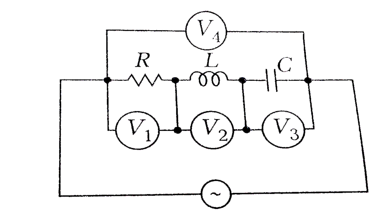
An ideal resistance R, ideal inductance L , ideal capacitance C and AC voltmeters V1 , V2 , V3 and V4 are connected to an AC source as shown . At resonance
 View Solution
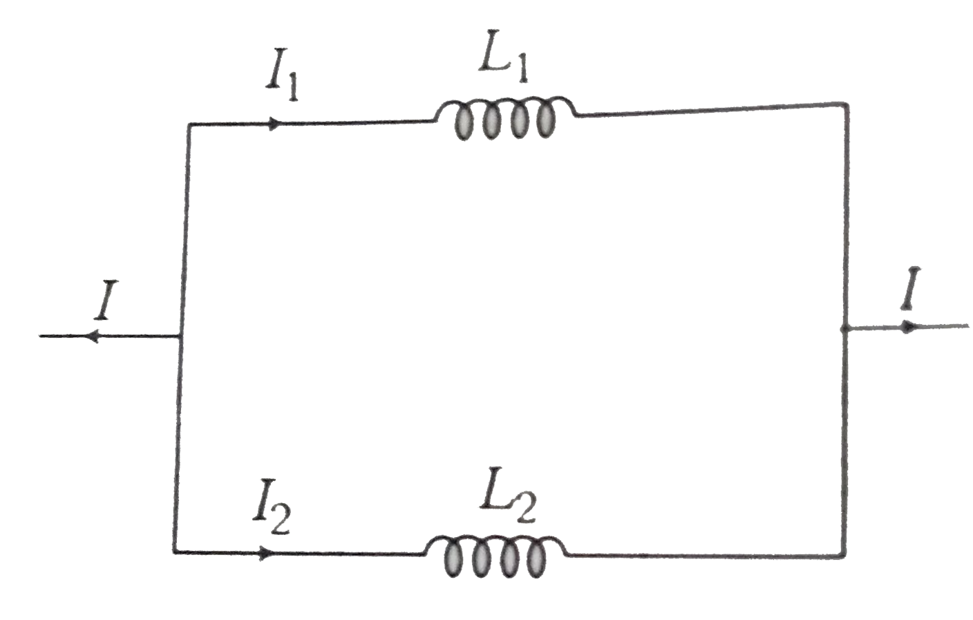
Two inductors L1and L2 are connected in parallel and a time varying current flows as shown in figure. Then the ratio currents l1 / l2 at any time t is
 View Solution
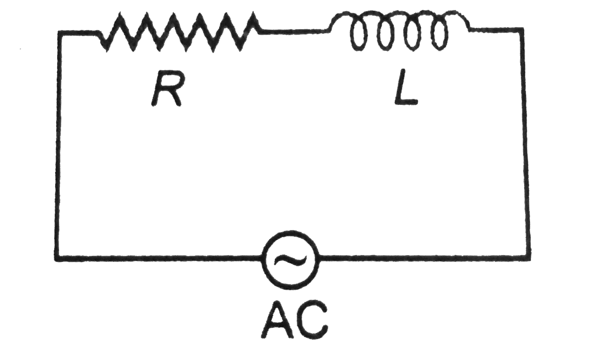
A circuit contains resistance R and an inductance L in series. An alternating voltage V=V0sinωt is applied across it. The currents in R and L respectively will be
 .View Solution
A circuit contains resistance R and an inductance L in series. An alternating voltage V=V0sinωt is applied across it. The currents in R and L respectively will be
 .View Solution
An L-C-R series is under resonance . If lm is current amplitude Vm is voltage amplitude, R is the resonance , Z is the impedance , XL is the inducitve reactance and XC is the capacitive reactance , then
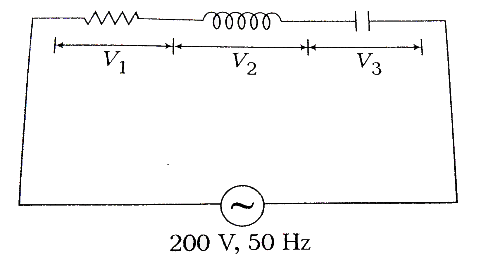
View SolutionFor series L-C-R circuit shown in the figure, the readings of V2 and V3 are same and each equal to 100 V .Then
 View Solution
In
−NO2(i),−NH2(ii),−SO3H(iii) ,
The decreasing order of -I effect isView SolutionFigures shows a parallel LCR circuit connected to a 200V, AC source. L=5H, C=80μFandR=40Ω. At resonance let I1andi2 be the rs currents through L,C and R. Then
 View Solution
The correct IUPAC name of the given compound is
I−C∣F=C∣Cl−C≡C−OCH2View SolutionThe reaction
R−C∣∣O−RN3H−−−→H2SO4RCONHR+N2 is calledView Solution

