An AC source of variable frequency f is connected to an LCR series circuit. Which one of the graphs in figure represents the variation of current of current I in the circuit with frequecy f?
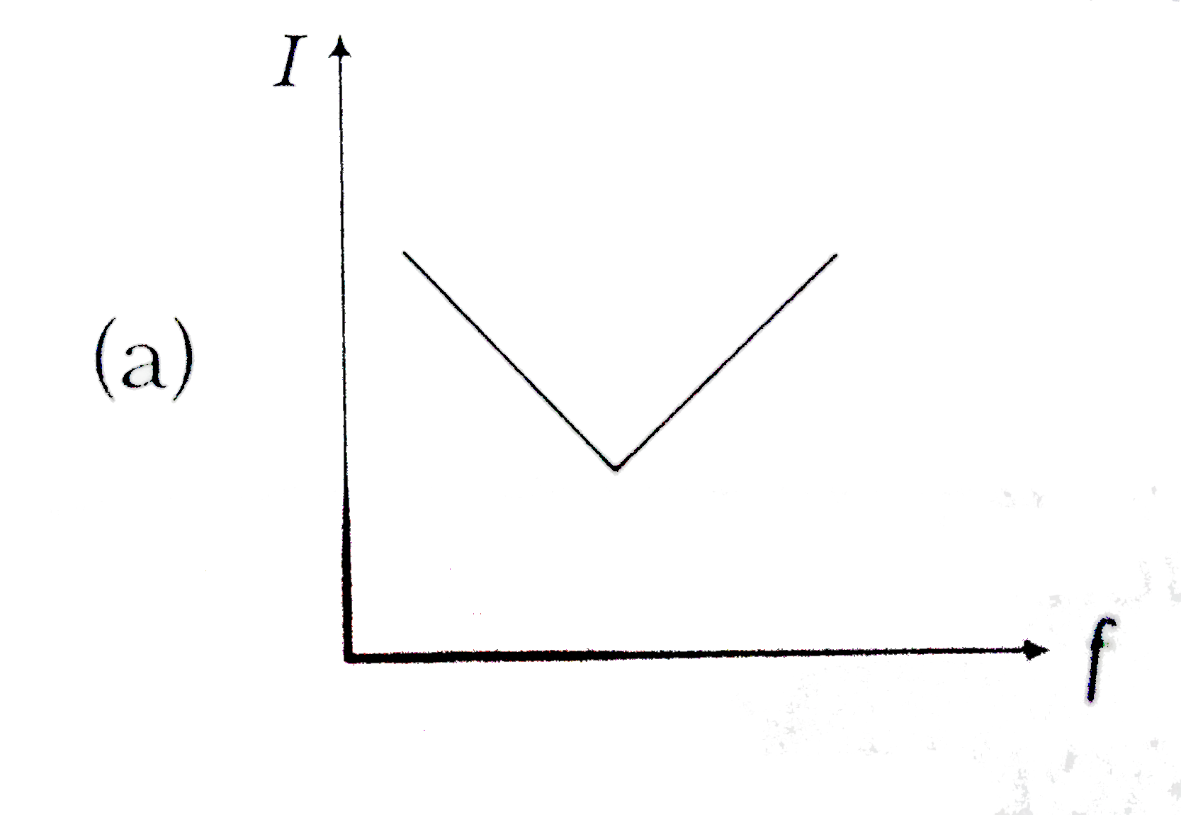
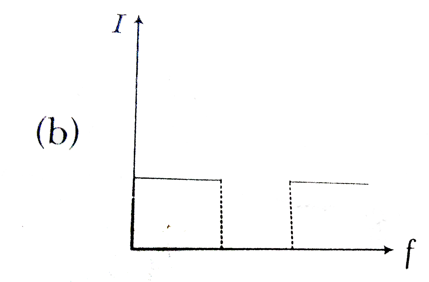
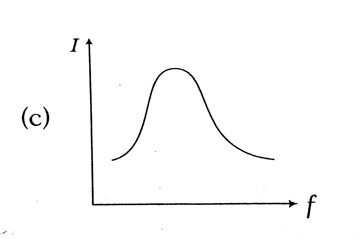
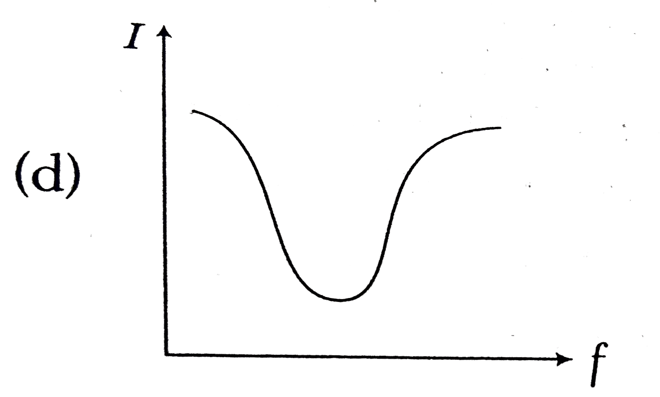
The correct Answer is:C
To solve the problem, we need to analyze how the current I in an LCR series circuit varies with frequency f. Here’s the step-by-step solution:
Step 1: Understanding the LCR Circuit
In an LCR series circuit, the total current I is determined by the voltage V applied and the total impedance Z of the circuit. The impedance Z is given by:
Z=√R2+(XL−XC)2
where:
- R is the resistance,
- XL=ωL=2πfL is the inductive reactance,
- XC=1ωC=12πfC is the capacitive reactance.
Step 2: Expression for Current
The current I can be expressed as:
I=VZ
Substituting the expression for Z:
I=V√R2+(XL−XC)2
Step 3: Analyzing Resonance
At resonance frequency f0, the inductive reactance equals the capacitive reactance (XL=XC). This occurs when:
2πf0L=12πf0C
From this, we can find the resonance frequency:
f0=12π√LC
At this frequency, the impedance Z is minimized to R, leading to maximum current:
Imax=VR
Step 4: Current Variation with Frequency
- For frequencies below f0, XC>XL leading to higher impedance and lower current.
- For frequencies above f0, XL>XC also leading to higher impedance and lower current.
- Therefore, the current I reaches its maximum value at the resonance frequency f0 and decreases as we move away from this frequency in either direction.
Step 5: Identifying the Correct Graph
From the analysis, we conclude that the graph representing the current I as a function of frequency f will show a peak at the resonance frequency f0. This corresponds to option C, where the current is maximum at a specific frequency and decreases on either side of that frequency.
Conclusion
The correct answer is option C, which shows that the current I in the circuit varies with frequency f such that it is maximum at the resonance frequency and decreases for frequencies away from resonance.
---
In an LCR series circuit, the total current I is determined by the voltage V applied and the total impedance Z of the circuit. The impedance Z is given by:
Z=√R2+(XL−XC)2
where:
- R is the resistance,
- XL=ωL=2πfL is the inductive reactance,
- XC=1ωC=12πfC is the capacitive reactance.
The current I can be expressed as:
I=VZ
Substituting the expression for Z:
I=V√R2+(XL−XC)2
At resonance frequency f0, the inductive reactance equals the capacitive reactance (XL=XC). This occurs when:
2πf0L=12πf0C
From this, we can find the resonance frequency:
f0=12π√LC
At this frequency, the impedance Z is minimized to R, leading to maximum current:
Imax=VR
- For frequencies below f0, XC>XL leading to higher impedance and lower current.
- For frequencies above f0, XL>XC also leading to higher impedance and lower current.
- Therefore, the current I reaches its maximum value at the resonance frequency f0 and decreases as we move away from this frequency in either direction.
From the analysis, we conclude that the graph representing the current I as a function of frequency f will show a peak at the resonance frequency f0. This corresponds to option C, where the current is maximum at a specific frequency and decreases on either side of that frequency.
The correct answer is option C, which shows that the current I in the circuit varies with frequency f such that it is maximum at the resonance frequency and decreases for frequencies away from resonance.
Similar Questions
Knowledge Check
If a variable frequency ac source is connected to a capacitor then with decrease in frequency the displacement current will
AincreaseBdecreaseCremains constantDfirst decrease then increaseAt resonant frequency the current amplitude in series LCR circuit is
AmaximumBminimumCzeroDinfinity
For an LCR series circuit with an aac source of angular frequency ω.
View SolutionWhen an AC voltage, of variable frequency is applied to series L-C-R circuit , the current in the circuit is the same at 4 kHz and 9 kHz. The current in the circuit is maximum at
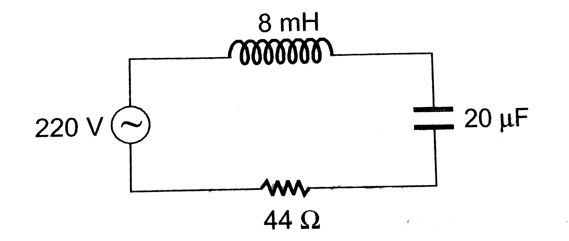
View SolutionFor the series LCR circuit shown in the figure, what is the resonance frequency and the amplitude of the current at the resonating frequency

View SolutionFor the series LCR circuit shown in the figure, what is the resonance frequency and the amplitude of the current at the resonating frequency
View SolutionA student in a lab took a coil and connected it to a 12VDC source. He measures the steady state current in the circuit to be 4A. He then replaced the 12VDC source by a 12V,(ω=50rads)AC source and observes that the reading in the AC ammeter is 2.4A. He then decides to connect a 2500μF capacitor in series with the coil and calculate the average power developed in the circuit. Further he also decides to study the variation in current in the circuit (with the capacitor and the battery in series).
Which of the following graph roughly matches the variation of current in the circuit (with the coil and capacitor connected in the series) when the angulr frequency is decreased from 50 rad/s to 25 rad/s?
View SolutionAn AC source is connected to the LC series circuit with V=10sin(314t). Find the current in the circuit as function of time ? (L=40mH,C=100μF)
View Solution