The adjacent diagram Fig 1.27 shows a heavy roller, with its axle at O, which is to be raised on a pavement XY. IF there is friction between the roller and pavement, show by an arrow on the diagram the point of application and the direction of force to be applied. If pivoted at O, now will it go up?
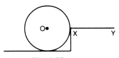
Step by step video & image solution for The adjacent diagram Fig 1.27 shows a heavy roller, with its axle at O, which is to be raised on a pavement XY. IF there is friction between the roller and pavement, show by an arrow on the diagram the point of application and the direction of force to be applied. If pivoted at O, now will it go up? by Physics experts to help you in doubts & scoring excellent marks in Class 10 exams.
Updated on:21/07/2023Topper's Solved these Questions
- FORCE BOOK - ICSECHAPTER - FORCE EXERCISE - EXERCISE 1(A) Multiple choice questions
2 Videos
- FORCE BOOK - ICSECHAPTER - FORCE EXERCISE - EXERCISE 1(A) Numericals
18 Videos
- FORCE BOOK - ICSECHAPTER - FORCE EXERCISE - EXERCISE 1( C) Multiple Choice questions
2 Videos
- ELECTRO-MAGNETISM BOOK - ICSECHAPTER - ELECTRO-MAGNETISM EXERCISE - EXERCISE-10 (C) NUMERICALS
1 Videos
- HOUSEHOLD CIRCUITS BOOK - ICSECHAPTER - HOUSEHOLD CIRCUITS EXERCISE - EXERCISE -9(B) (MULTIPLE CHOICE TYPE)
2 Videos
Similar Questions
The figure alongside shows an axle AB pivoted at a point 0. Draw diagrams showing the point of application and direction of minimum force to rotate it (b) clockwise, and (ii) anticlockwise.

View SolutionThe figure alongside shows an axle AB pivoted at a point 0. Draw diagrams showing the point of application and direction of minimum force to rotate it (b) clockwise, and (ii) anticlockwise.

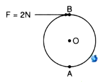
View SolutionA wheel of diameter 2m is shown in Fig 1.28 with axle at O. At force F= 2N is applied at B in the direction shown in figure, Calculate the moment of force about (i) the centre O, and (ii) the point A.
View SolutionThe diagram below (Fig.1.32) shows a uniform bar supported at the middle O. A weight of 40gf is placed at a distance 40cm to the left of point O. How can you balance the bar with the weight of 80gf.

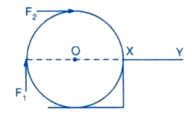
View SolutionIn Fig. 1.17 a roller of diameter 0.4m is raised on the pavement XY by forces F1andF2 each of magnitude 10N. Compare the torques produced by the two forces.
View SolutionDraw a neat labelled diagram to show the direction of two forces acting on a body to produce rotation in it. Also mark the point O about which the rotation takes place.
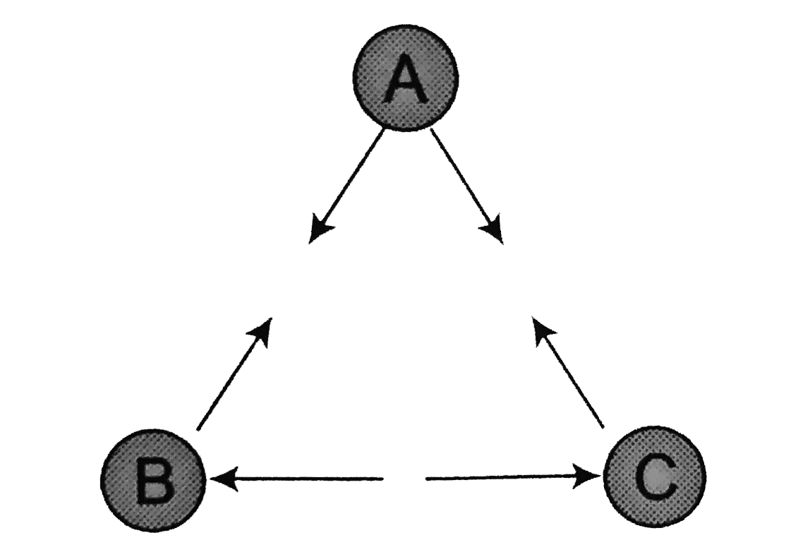
View SolutionThe diagram shows the arrangement of three small uniformally charged spheres, A,B and C. The arrow indicate the direction of the electrostatic forces acting between the spheres (for example, the left arrow on sphere A indicates the electronstatic force on sphere A due to sphere B). At least two of the spheres are positively charged. Which sphere, if any, could be negatively charged?
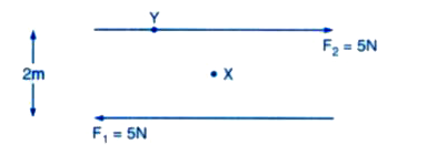
View SolutionThe following diagram (Fig. 1.20) shows two parallel and opposite forces F1andF2 each of magnitude 5N, with their lines of action separated by a distance of 2m. A point X is pivoted midway between F1andF2 while a point Y is pivoted on F2
(a) calculate the total moment of the two forces about the points (i) X, and (ii) Y
(b) State the effect produced by the two forces about the points (i) X and (ii) Y
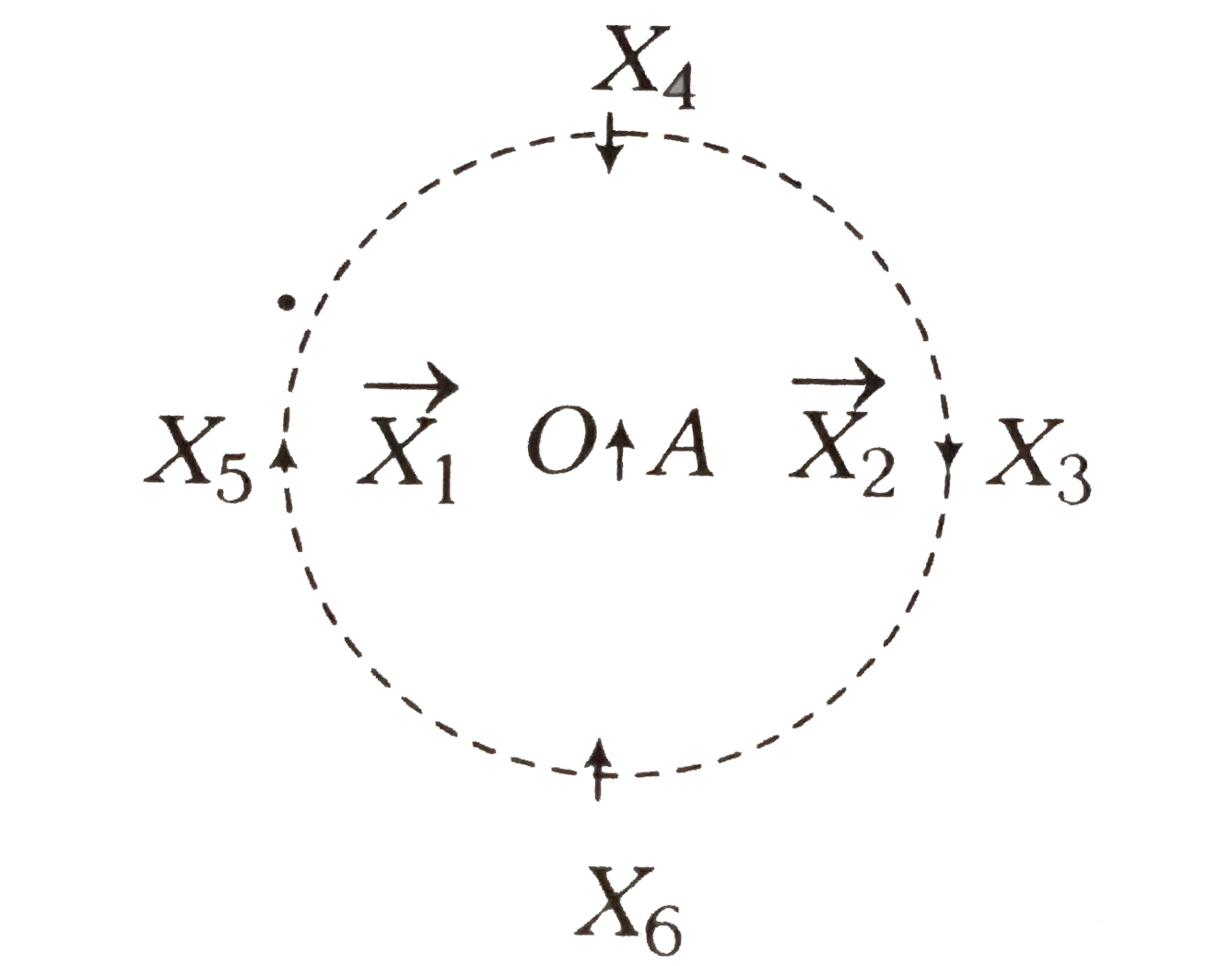
View SolutionConsider the situation shown in the diagram, where A small magnetised needle A is placed at a centre marked, as O. The direction of its mangetic moment I s indicated by arrow. The other arrow show different position (and orientations of the magnetic moment) of antoher identical magnetised eedle X.
In which configuration the system is not in equlibrium?
(ii) In which configuration is the system in (a) stable and (b) unsable equilibrium
(iii) Which configuration corresponds to the lowest potentials energy among all the configuration shown
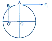
View SolutionThe wheel shown in the diagram (Fig.1.18) has a fixed axle passing through O. The wheel is kept stationary under the action of (i) a horizontal force F1 at A and (ii) a vertical force F2 at B.
(a) Show the direction of force F2 in the diagram.
(ii) Which of the force F1orF2 is greater
(c) Find the ratio between the forces F1andF2 Given: AO =2.5 cm
BO'=1.5 cm and O'O=2.0cm
View Solution
