A horse shoe magnet has two iron needles attached at its ends. Show on a diagram the positions occupied by the needles and name the phenomenon which comes into play.
To solve the question regarding the horse shoe magnet with two iron needles, we will follow these steps:
Step 1: Draw the Diagram
Begin by sketching a horse shoe magnet. The magnet should have a clear distinction between its north and south poles.
- North Pole: Label one end of the horse shoe magnet as the North Pole (N).
- South Pole: Label the other end as the South Pole (S).
Step 2: Position the Iron Needles
Next, draw two iron needles, one attached to each end of the horse shoe magnet.
- Needle 1: Place the first iron needle at the North Pole end of the magnet.
- Needle 2: Place the second iron needle at the South Pole end of the magnet.
Step 3: Indicate the Attraction
Indicate the attraction between the needles and the poles of the magnet. Since the North Pole of the magnet attracts the South Pole of the needles and vice versa, draw arrows showing this attraction.
Step 4: Name the Phenomenon
Finally, state the phenomenon that is occurring. The phenomenon by which the iron needles become magnetized and are attracted to the poles of the magnet is known as Magnetic Induction.
Final Diagram:
Your final diagram should clearly show:
- The horse shoe magnet with its North and South poles labeled.
- The two iron needles positioned at each pole.
- Arrows indicating the attraction between the needles and the poles.
- A note stating "Phenomenon: Magnetic Induction".
Begin by sketching a horse shoe magnet. The magnet should have a clear distinction between its north and south poles.
- South Pole: Label the other end as the South Pole (S).
Next, draw two iron needles, one attached to each end of the horse shoe magnet.
- Needle 2: Place the second iron needle at the South Pole end of the magnet.
Indicate the attraction between the needles and the poles of the magnet. Since the North Pole of the magnet attracts the South Pole of the needles and vice versa, draw arrows showing this attraction.
Finally, state the phenomenon that is occurring. The phenomenon by which the iron needles become magnetized and are attracted to the poles of the magnet is known as Magnetic Induction.
Your final diagram should clearly show:
- The horse shoe magnet with its North and South poles labeled.
- The two iron needles positioned at each pole.
- Arrows indicating the attraction between the needles and the poles.
- A note stating "Phenomenon: Magnetic Induction".
Topper's Solved these Questions
- BOOK - ICSECHAPTER - MAGNETISM EXERCISE - EXERCISE-10(A)39videos
MAGNETISM
- BOOK - ICSECHAPTER - MAGNETISM EXERCISE - EXERCISE-10(A) (Multiple Choice Type)2videos
MAGNETISM
- BOOK - ICSECHAPTER - LIGHTEXERCISE - TOPIC 2 Spherical Mirrors (4 Marks Questions )9videos
LIGHT
- BOOK - ICSECHAPTER - MEASUREMENTS AND EXPERIMENTATION EXERCISE - TOPIC 2 SIMPLE PENDULUM (4 Marks Questions )1videos
MEASUREMENTS AND EXPERIMENTATION
Similar Questions
Figure shows the section of a semi-circular glass slab having its centre at O. three rays of light A,B and C of the same colour are incident on the slab and strike on the edge XY at the point O. the light ray B suffers refraction along OB'.
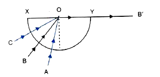
(a) On the diagram, mark the critical angle by C.
(b) The rays enter the slab undeviated. give reason.
(c) Draw the path of rays A and C after they strike the edge XY.
(d) Name the phenomenon which the rays A and C exhibit.View SolutionA rigid massless rod of length 3l has two masses attached at each end as shown in the figure. The rod is pivoted at point P on the horizontal axis (see figuare). When released from initial horizontal position, its instantaneous angular acceleration will be
 View Solution
The figure shows top view of a conducting rob AB, bent to form a semicircle of radius R, carrying current I, placed on a smooth horizontal table. It is subjected to a uniform magnetic field B perpendicular to its plane as shown. The rod is held at rest in its position by two light strings attached to its ends. Calculate the magnetic force acting on the conductor AB and the tension in the strings.
Strategy: To find the force conductor, consider a small arc of length dl=Rdθ. This arc can be consider as a straight conductor of length dl.View SolutionName the two parts with which the ear bone stapes is attached at its opposite ends.
View SolutionA student puts his pencil into an empty trough and observes the pencil from the position as indicated in Figure.
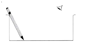
(i) What change will be observed in the appearance of the pencil when water is poured into the trough?
(ii) Name the phenomenon which accounts for the above stated observation.
(iii) Complete the diagram showing how the student's eye sees the pencil through water.View SolutionFigure shows a spool with thread wound on it placed on a smooth plane inclined at angle from horizontal. The spool has mass m, edge radius R, and is wound up to a radius r. its moment of inertia about its own axis is I. The free end of the thread is attached as shown in the figure. So that the thread is parallel to the inclined plane. T is the tension in the thread. Which of the following is correct?
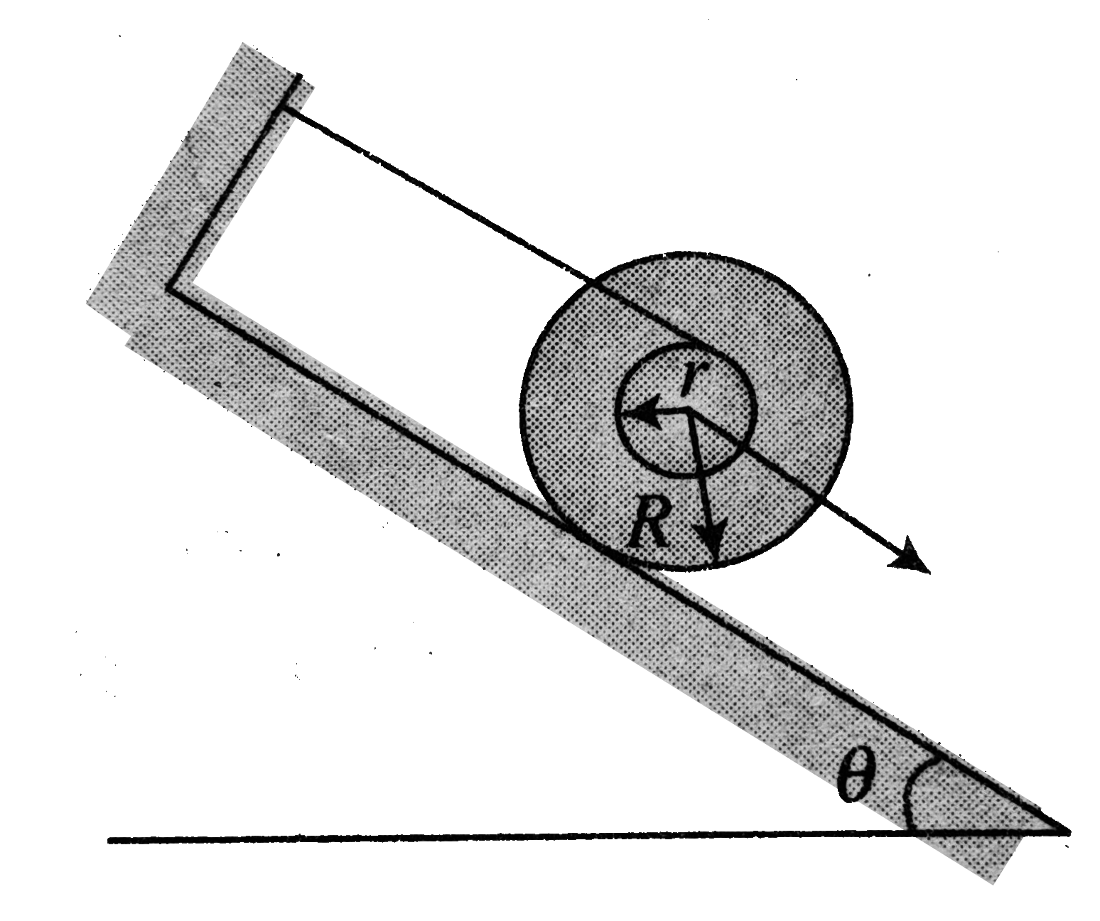 View Solution
The diagram below shows a magnetic needle kept just below the conductor AB which is kept in North South direction.
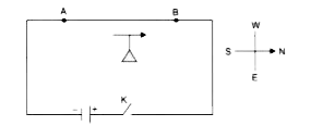
In which direction will the needle deflect when the key is closed ?View SolutionA dip circle is adjusted so that its needle moves freely in the magnetic meridian. In this position, the angle of dip ia 40∘. Now the dip circle is rotated so that the plane in which the needle moves makes an angle of 30∘ with the magnetic meridian. In this position the needle will dip by an angle
View SolutionA deflection magnetometer is placed with its arm along the east-west direction (tan A position) and a short bar magnet is placed symmetrically along its axis at some distance with its north pole pointing towards east. In this position the needle of the magnetometer shows a deflection of 60∘. If we double the distance of the bar magnet, then the deflection will be
View SolutionA metal rod of length 'L' and mass 'm' is pivoted at one end. A thin disk of mass 'M' and radius 'R' (< L) is attached at its centre to the free end of the rod. Consider two ways the disc is attached: (case A) - The disc is not free to rotate about its centre and (case B) - the disc is free to rotate about its centre. The rod-disc system after being released from the same displaced position. Which of the following statement(s) is(are) true?
 View Solution

