Draw a circuit diagram for the determination of the internal resistance of a cell using potentiometer. Derive the formula to be used.
To determine the internal resistance of a cell using a potentiometer, we can follow these steps:
Step 1: Draw the Circuit Diagram
1. Components Required:
- A potentiometer wire (P)
- A galvanometer (G)
- A cell of EMF (E)
- A rheostat (R)
- A resistance box (RB)
- A switch (K)
- Connecting wires
2. Circuit Arrangement:
- Connect the potentiometer wire in series with the galvanometer.
- Connect the cell (E) in series with the resistance box (RB) and the rheostat (R).
- Use the switch (K) to control the connection of the cell to the circuit.
Circuit Diagram:
±−−−(E)−−−−(RB)−−−−(R)−−−−K−−−−+||∣||∣±−−−(P)−−−−(G)−−−−−−−−−−−−−−−+
Where:
- (E) is the cell whose internal resistance we want to measure.
- (RB) is the resistance box.
- (R) is the rheostat.
- (P) is the potentiometer wire.
- (G) is the galvanometer.
Step 2: Understanding the Working Principle
1. When the switch K is closed, the current flows through the circuit.
2. Adjust the rheostat to find the balancing length (l1) on the potentiometer wire when the key K1 is open.
3. The EMF of the cell (E) can be expressed as:
\(
E = k \cdot l_1
\)
where k is the potential gradient of the potentiometer.
4. When both switches K and K1 are closed, the galvanometer shows a new balancing length (l2). The potential across the external circuit can be expressed as:
\(
V = k \cdot l_2
\)
Step 3: Deriving the Formula for Internal Resistance
1. The total voltage across the circuit can be expressed as:
\(
E = V + I \cdot r
\)
where:
- I is the current flowing through the circuit.
- r is the internal resistance of the cell.
2. Rearranging gives:
\(
I \cdot r = E - V
\)
3. Substituting the expressions for E and V:
\(
I \cdot r = k \cdot l_1 - k \cdot l_2
\)
4. This can be simplified to:
\(
I \cdot r = k \cdot (l_1 - l_2)
\)
5. Now, using Ohm's law, we can express the current (I) as:
\(
I = \frac{E}{R + r}
\)
6. Substituting this into the equation gives:
\(
\frac{E}{R + r} \cdot r = k \cdot (l_1 - l_2)
\)
7. Rearranging to solve for r gives:
\(
r = \frac{k \cdot (l_1 - l_2) \cdot R}{E - k \cdot (l_1 - l_2)}
\)
Final Formula:
The formula for the internal resistance \( r \) of the cell is:
\(
r = \frac{R \cdot (l_1 - l_2)}{l_2}
\)
1. Components Required:
- A potentiometer wire (P)
- A galvanometer (G)
- A cell of EMF (E)
- A rheostat (R)
- A resistance box (RB)
- A switch (K)
- Connecting wires
- Connect the potentiometer wire in series with the galvanometer.
- Connect the cell (E) in series with the resistance box (RB) and the rheostat (R).
- Use the switch (K) to control the connection of the cell to the circuit.
±−−−(E)−−−−(RB)−−−−(R)−−−−K−−−−+||∣||∣±−−−(P)−−−−(G)−−−−−−−−−−−−−−−+
Where:
- (E) is the cell whose internal resistance we want to measure.
- (RB) is the resistance box.
- (R) is the rheostat.
- (P) is the potentiometer wire.
- (G) is the galvanometer.
1. When the switch K is closed, the current flows through the circuit.
2. Adjust the rheostat to find the balancing length (l1) on the potentiometer wire when the key K1 is open.
3. The EMF of the cell (E) can be expressed as:
\(
E = k \cdot l_1
\)
where k is the potential gradient of the potentiometer.
\(
V = k \cdot l_2
\)
1. The total voltage across the circuit can be expressed as:
\(
E = V + I \cdot r
\)
where:
- I is the current flowing through the circuit.
- r is the internal resistance of the cell.
\(
I \cdot r = E - V
\)
\(
I \cdot r = k \cdot l_1 - k \cdot l_2
\)
\(
I \cdot r = k \cdot (l_1 - l_2)
\)
\(
I = \frac{E}{R + r}
\)
\(
\frac{E}{R + r} \cdot r = k \cdot (l_1 - l_2)
\)
\(
r = \frac{k \cdot (l_1 - l_2) \cdot R}{E - k \cdot (l_1 - l_2)}
\)
The formula for the internal resistance \( r \) of the cell is:
\(
r = \frac{R \cdot (l_1 - l_2)}{l_2}
\)
Similar Questions
Knowledge Check
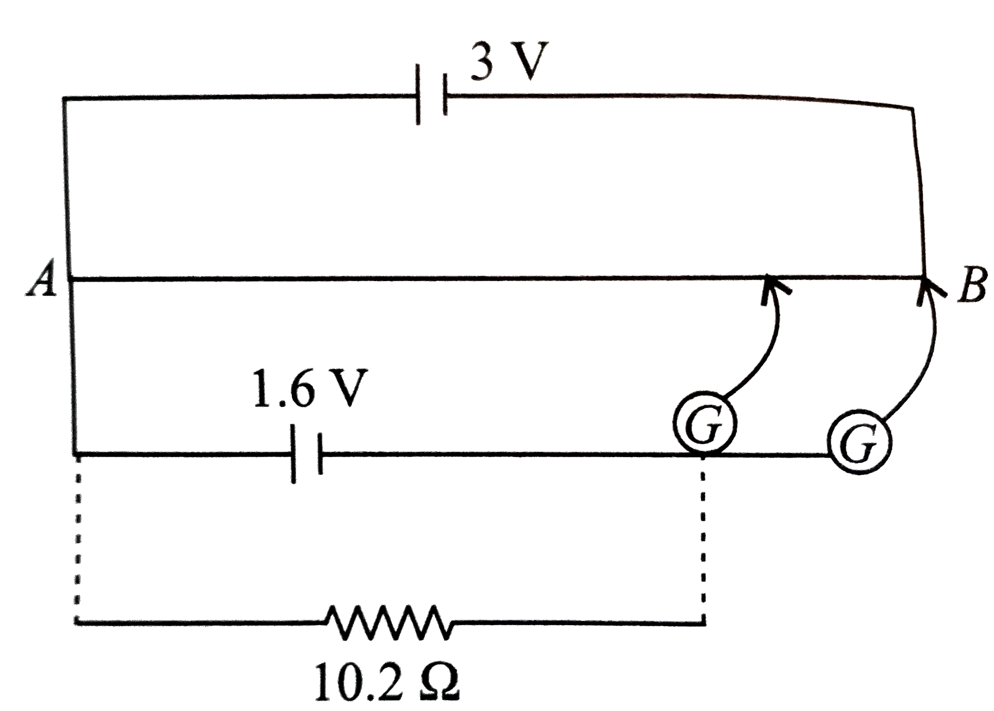
3V poteniometer used for the determination of internal resistance of a 2.4V cell. The balanced point of the cell in open circuit is 75.8cm. When a resistor of 10.2Ω is used in the external circuit of the cell the balance point shifts to 68.3cm length of the potentiometer wire. The internal resistance of the cell is
 A2.5ΩB2.25ΩC1.12ΩD3.2Ω
Describe the method of determination of surface tension of a liquid by capillary rise. Derive the formula used.
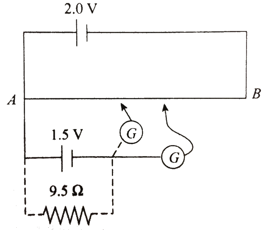
View SolutionFigure 6.13 shows a 2.0V potentiometer used for the determination of internal resistance of a 1.5V cell. The balance point of the cell in open circuit is 76.3cm. Whan a resistor of 9.5Ω is used in the external circuit of the cell, the balance point shifts to 64.8cm, length of the potentiometer. Dentermine the internal resistance of the cell.

View SolutionDraw a diagram of the internal structure of the human ovary.
View SolutionIn an experiment to determine the internal resistance of a cell with potentiometer, the balancing length is 165 cm. When a resistance of 5 ohm is joined in parallel with the cell the balancing length is 150 cm. The internal resistance of cell is
View SolutionDraw a diagram to illustrate the determination of the focal length of a convex lens using an auxiliary plane mirror.
View SolutionA potentiometer can be used to measure
View SolutionIn order to determine the internal resistance of a primary cell by means of potentiometer the emf of the battery connected across the ends of the potentiometer wire should be
View Solution
