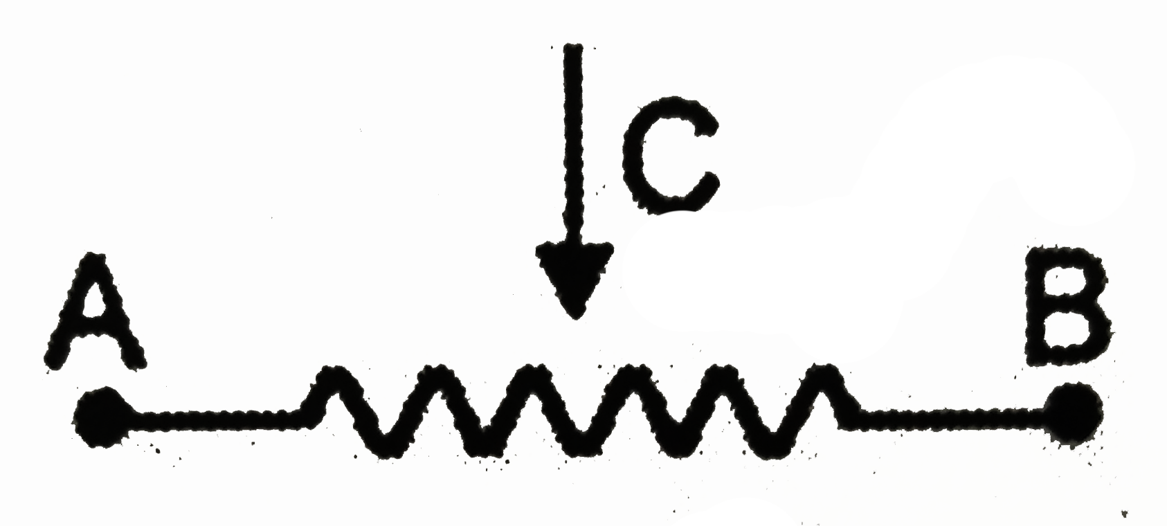
(a)Complete the circuit given in Fig. by inserting between the terminals A and C. an ammeter.
(b) In the diagram, mark the polarity at the terminals of ammeter and indicate clearly the direction of flow of current in the circuit when the circuit is complete.
(c) Name and state the purpose of Rh in the circuit.

(a) and (b)

(c ) Rh is a rheostat. Rheostat is variable resistor. With the help of this the current in the ciruit may be controlled by varying the resistance.
Topper's Solved these Questions
- ELECTRICITY AND MAGNETISM BOOK - ICSECHAPTER - ELECTRICITY AND MAGNETISM EXERCISE - TOPIC 2 Magnetism (2 Marks Questions )
13 Videos
- ELECTRICITY AND MAGNETISM BOOK - ICSECHAPTER - ELECTRICITY AND MAGNETISM EXERCISE - TOPIC 2 Magnetism (3 Marks Questions )
4 Videos
- ELECTRICITY AND MAGNETISM BOOK - ICSECHAPTER - ELECTRICITY AND MAGNETISM EXERCISE - TOPIC 1 Electric Circuit (3 Marks Questions )
9 Videos
- CURRENT ELECTRICITYBOOK - ICSECHAPTER - CURRENT ELECTRICITYEXERCISE - Exercise-9(C ) Multiple choice
2 Videos
- FLUIDSBOOK - ICSECHAPTER - FLUIDSEXERCISE - TOPIC 2 (4 Marks Questions )
16 Videos
Similar Questions
(a) Complete the circuit given in Fig. 1 by inserting between the terminals A and C, an ammeter. (b) In the diagram mark the polarity at the terminals of ammeter and indicate clearly the direction of flow of current in the circuit, when the circuit is complete. (c) Name and state the purpose of Rh in the circuit.

View SolutionThe equivalent resistane of the given circuit between the terminals A and B is :

View Solution
Knowledge Check
The peak value of current in the circuit when the reading of an ammeter is 4 A is given by
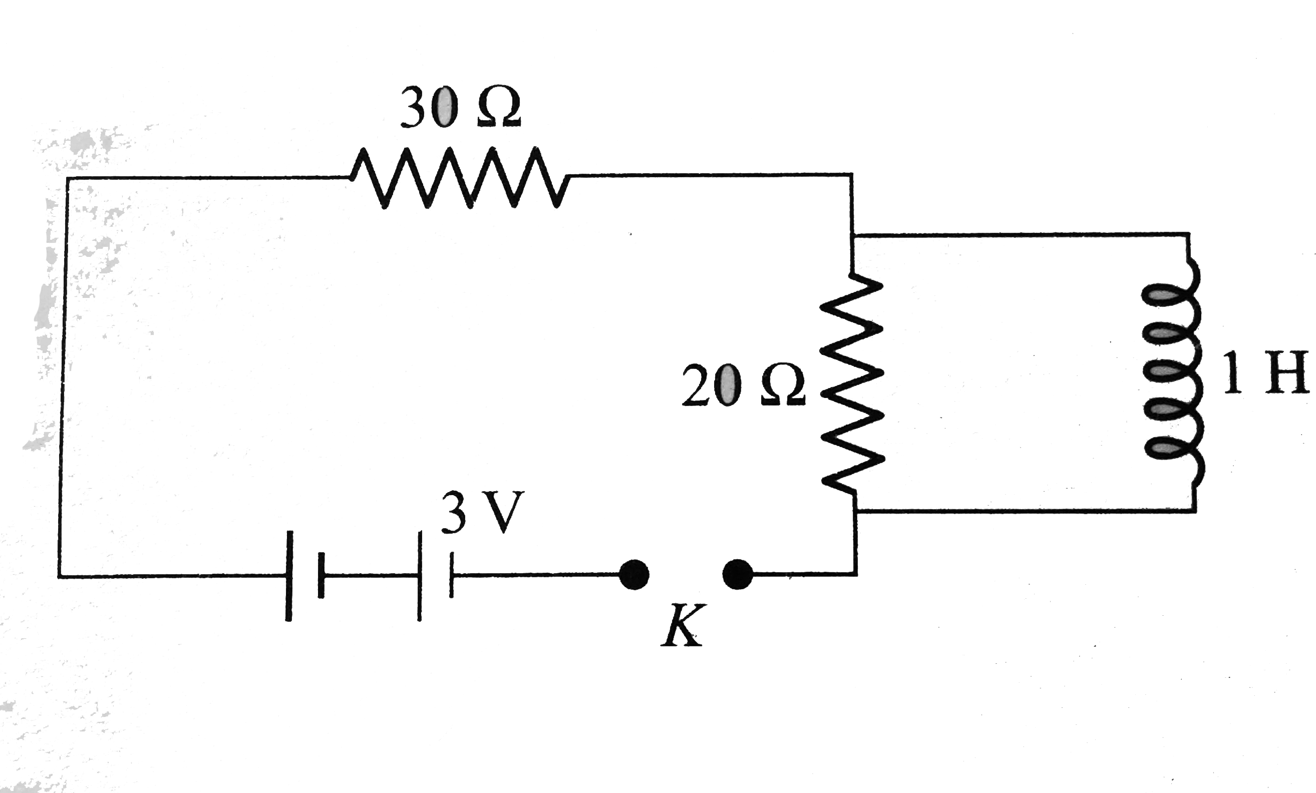
A8AB4AC4√2AD2√2AIn the circuit Fig the final current through 30Ω resistance when circuit is completed is
 A3AB0.1AC5AD0.5A
In the circuit Fig the final current through 30Ω resistance when circuit is completed is

View SolutionThe time constant for LR circuit between the terminals a and b as shown in diagram is
View SolutionDraw a circuit diagram for a bulb connected to a cell with a switch. Mark arrows in the diagram to indicate the direction of flow of current.
View SolutionConnect a battery to the terminals and completer the circuit diagram fo that it works as a potential divider meter. Indicate the output terminals also.

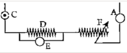
View SolutionIn the electric circuit shown in Fig., label the parts A, B, C, D, E, and E
State the function of each part. Show in the diagram the direction of flow of current.

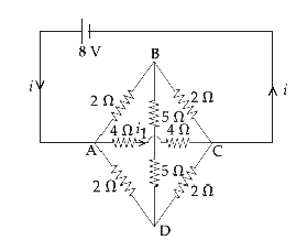
View SolutionThe value of current i1 flowing from A to C in the circuit diagram is :

View Solution
