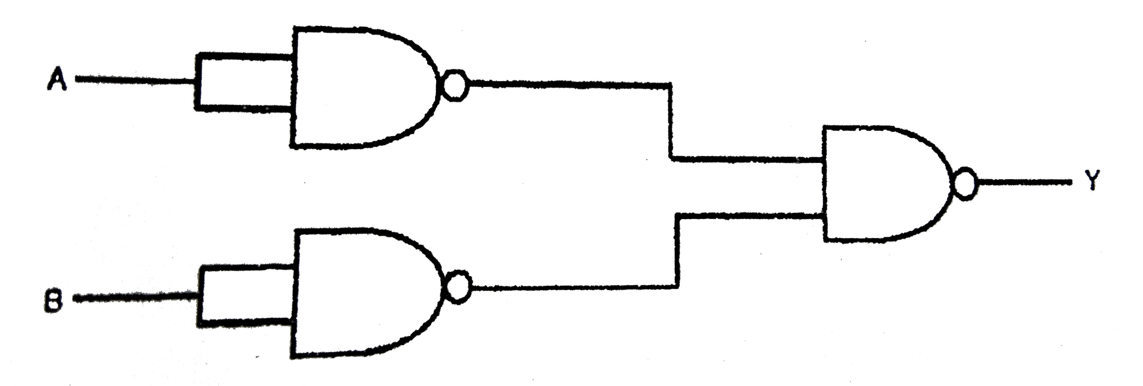
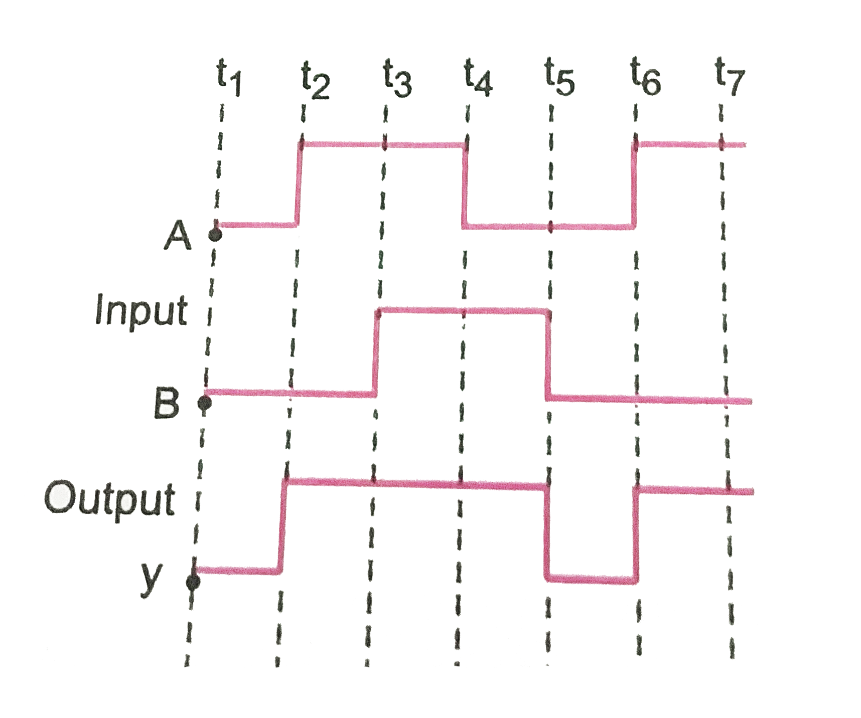
Show how you will obtain an AND gate using only NOR gates. Draw the truth table for this arrangement of gates.
To obtain an AND gate using only NOR gates, we can follow these steps:
Step 1: Understand the NOR Gate
A NOR gate is a digital logic gate that outputs true or high (1) only when both of its inputs are false or low (0). The output of a NOR gate can be expressed as:
\( \text{Output} = \overline{A + B} \)
where \( A \) and \( B \) are the inputs.
Step 2: Create NOT Gates Using NOR Gates
To create a NOT gate using a NOR gate, we can connect both inputs of the NOR gate to the same input signal. For example, to create NOT A:
\( \text{NOT A} = \overline{A + A} = \overline{A} \)
Similarly, for NOT B:
\( \text{NOT B} = \overline{B + B} = \overline{B} \)
Step 3: Create the AND Gate Using NOR Gates
To create an AND gate, we can use the following configuration:
1. Create NOT A and NOT B using NOR gates.
2. Use these outputs as inputs to another NOR gate.
The expression for the AND gate can be derived as follows:
1. First, we find NOT A and NOT B:
- NOT A = \( \overline{A} \)
- NOT B = \( \overline{B} \)
2. Next, we apply the NOR operation on these two outputs:
- \( \text{Output} = \overline{(\overline{A} + \overline{B})} \)
- This is equivalent to \( A \cdot B \) (AND operation).
Step 4: Draw the Circuit Diagram
The circuit diagram will consist of:
- Two NOR gates for NOT A and NOT B.
- One NOR gate that takes the outputs of these two NOR gates.
A−−−−|NOR⊢−NOTA||||B−−−−|NOR⊢−NOTB||∣|⊢−−|NOR⊢−Output(AANDB)
Step 5: Construct the Truth Table
Now, we will create the truth table for the AND gate constructed using NOR gates.
| A | B | NOT A | NOT B | NOT A + NOT B | Output (A AND B) |
|---|---|-------|-------|----------------|-------------------|
| 0 | 0 | 1 | 1 | 1 | 0 |
| 0 | 1 | 1 | 0 | 1 | 0 |
| 1 | 0 | 0 | 1 | 1 | 0 |
| 1 | 1 | 0 | 0 | 0 | 1 |
Final Output
Thus, we have successfully constructed an AND gate using only NOR gates and provided the corresponding truth table.
A NOR gate is a digital logic gate that outputs true or high (1) only when both of its inputs are false or low (0). The output of a NOR gate can be expressed as:
\( \text{Output} = \overline{A + B} \)
where \( A \) and \( B \) are the inputs.
To create a NOT gate using a NOR gate, we can connect both inputs of the NOR gate to the same input signal. For example, to create NOT A:
\( \text{NOT A} = \overline{A + A} = \overline{A} \)
Similarly, for NOT B:
\( \text{NOT B} = \overline{B + B} = \overline{B} \)
To create an AND gate, we can use the following configuration:
1. Create NOT A and NOT B using NOR gates.
2. Use these outputs as inputs to another NOR gate.
1. First, we find NOT A and NOT B:
- NOT A = \( \overline{A} \)
- NOT B = \( \overline{B} \)
2. Next, we apply the NOR operation on these two outputs:
- \( \text{Output} = \overline{(\overline{A} + \overline{B})} \)
- This is equivalent to \( A \cdot B \) (AND operation).
The circuit diagram will consist of:
- Two NOR gates for NOT A and NOT B.
- One NOR gate that takes the outputs of these two NOR gates.
Now, we will create the truth table for the AND gate constructed using NOR gates.
|---|---|-------|-------|----------------|-------------------|
| 0 | 0 | 1 | 1 | 1 | 0 |
| 0 | 1 | 1 | 0 | 1 | 0 |
| 1 | 0 | 0 | 1 | 1 | 0 |
| 1 | 1 | 0 | 0 | 0 | 1 |
Thus, we have successfully constructed an AND gate using only NOR gates and provided the corresponding truth table.
Similar Questions
Draw the truth table of a NOR gate.
View SolutionShow with the help of a diagram, how you will obtain an AND gate using only NAND gates, (Truth table is not required)
View Solution
Draw the truth table for the logic gate arrangement shown in the figure.
View SolutionThe truth table for the following combination of gates is :-
_E01_430_Q01.png)
View SolutionDraw a sumbol for NOR gate and write its truth table.
View SolutionHow many NAND gates used to form AND gate.
View SolutionWhat is the symbol of a NOR gate? Write its truth table.
View SolutionWhat is a NAND gate ? Write its truth table.
View SolutionDraw the symbol for AND gate and write its truth table.

View SolutionThe Fig shown input waveforms A and B to a logic gate. Draw the output waveform for an OR gate. Write the truth table for this logic gate and draw its logic symbol.

View Solution
