In the system is in steady state. Then
a. VA−VB=_______
b. VB−VC=______
c. VD−Ve=______
d. The energy stored in the circuit is "________"
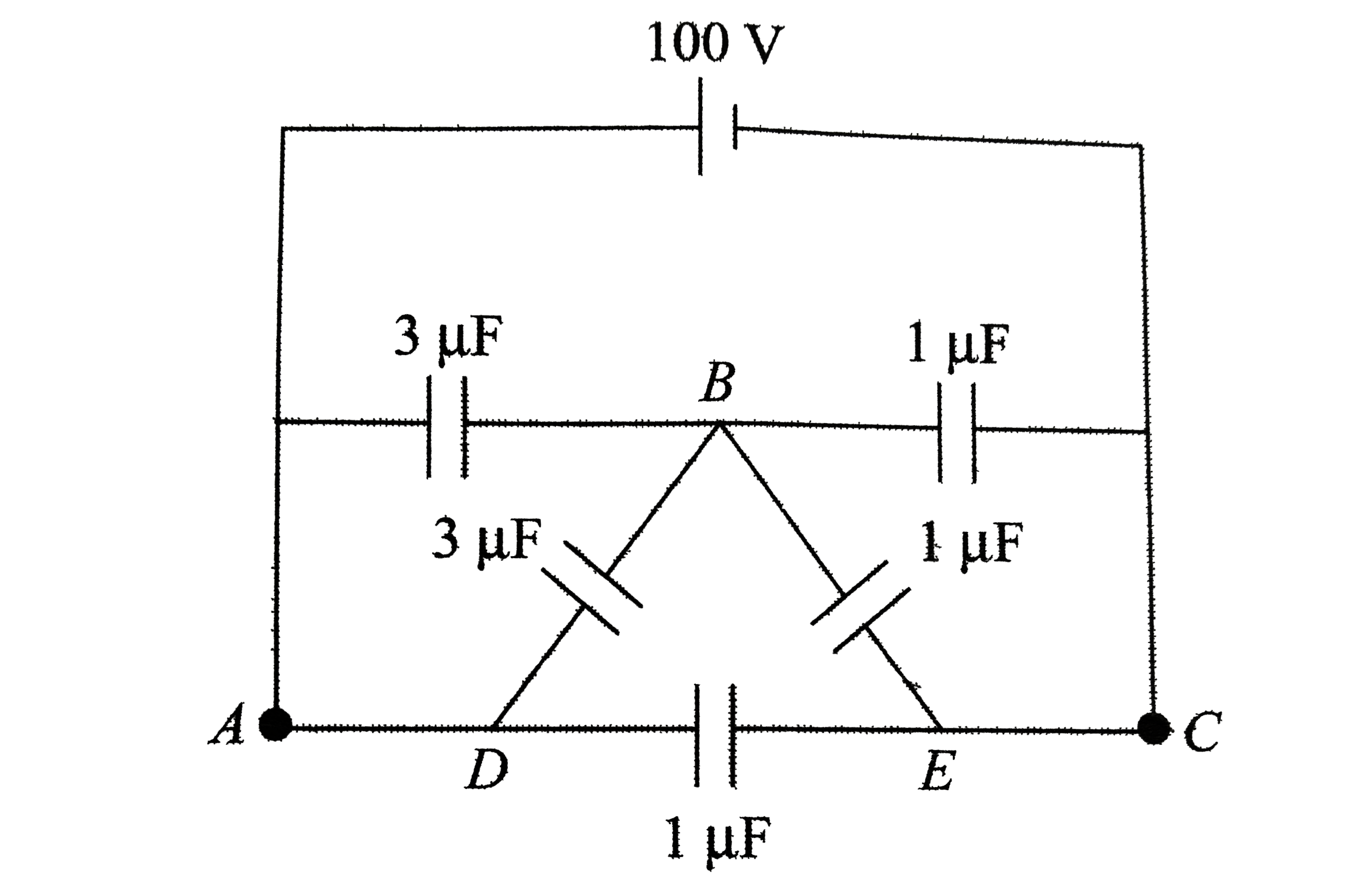 .
.
Video Solution
Text Solution
Both 3μF capacitors will be in parallel, and similarly upper two 1μF capacitors will be in parallel. The circuit may be redrawn as follows:
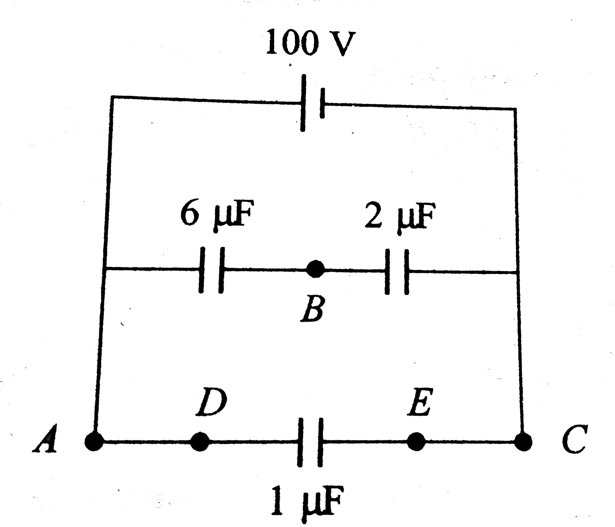 .
.
a. VA−VB=100×26+2=25V
b. VA−VC=100×66+2=75V
c. VD−VE=100V
d. Ceq=6×26+2+1=52μF
U=12CeqV2=12(52×10−6)×(100)2
=125×10−4J.
|
Topper's Solved these Questions
- CAPACITOR AND CAPACITANCEBOOK - CENGAGE PHYSICS ENGLISHCHAPTER - CAPACITOR AND CAPACITANCEEXERCISE - Subjective
24 Videos
- CAPACITOR AND CAPACITANCEBOOK - CENGAGE PHYSICS ENGLISHCHAPTER - CAPACITOR AND CAPACITANCEEXERCISE - Single Correct
49 Videos
- CAPACITOR AND CAPACITANCEBOOK - CENGAGE PHYSICS ENGLISHCHAPTER - CAPACITOR AND CAPACITANCEEXERCISE - Exercise 4.1
13 Videos
- ATOMIC PHYSICSBOOK - CENGAGE PHYSICS ENGLISHCHAPTER - ATOMIC PHYSICSEXERCISE - ddp.4.3
15 Videos
- CENGAGE PHYSICS DPPBOOK - CENGAGE PHYSICS ENGLISHCHAPTER - CENGAGE PHYSICS DPPEXERCISE - subjective type
51 Videos
Similar Questions
Find VA−VB in steady state
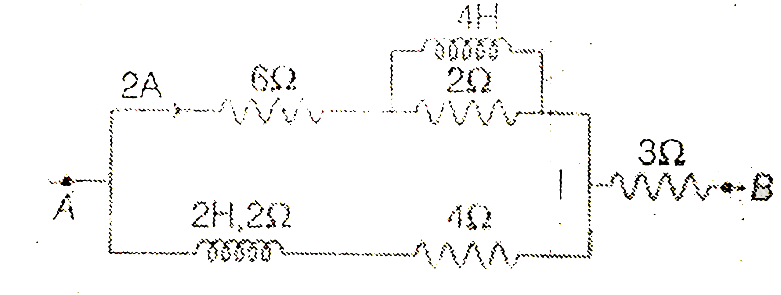
View SolutionPotential difference across AB , i.e., VA−VB is
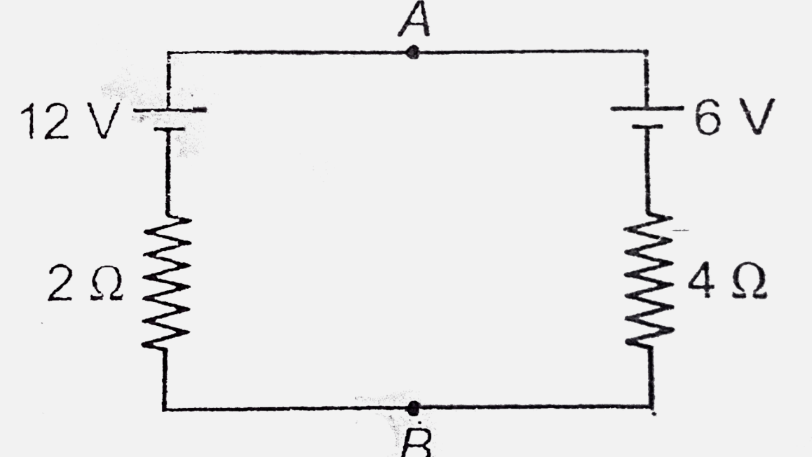
View SolutionVA−VB for given figure in steady state is
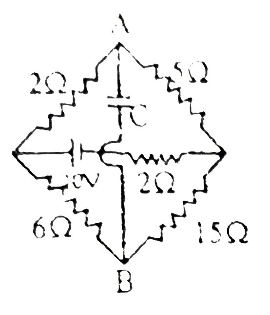
View SolutionConsider
 .
.
The potential difference VA−VB is.
View SolutionIn uniform electric field E=10N/C, find
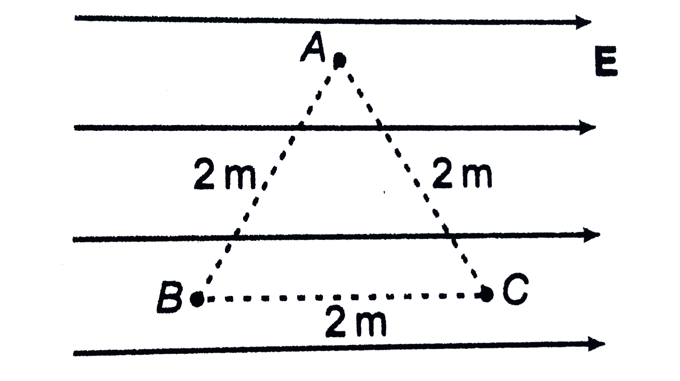
a. VA−VB , b. VB−VC
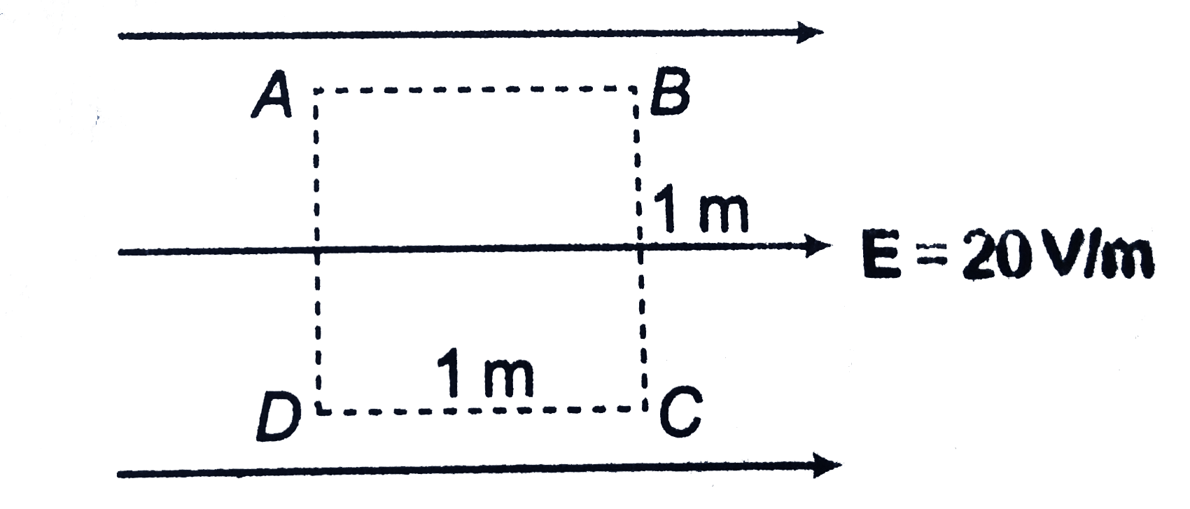
View SolutionIn the uniform electric field shown in figure, find :
a. VA−VD
b. VA−VC
c. VB−VD
d. VC−VD
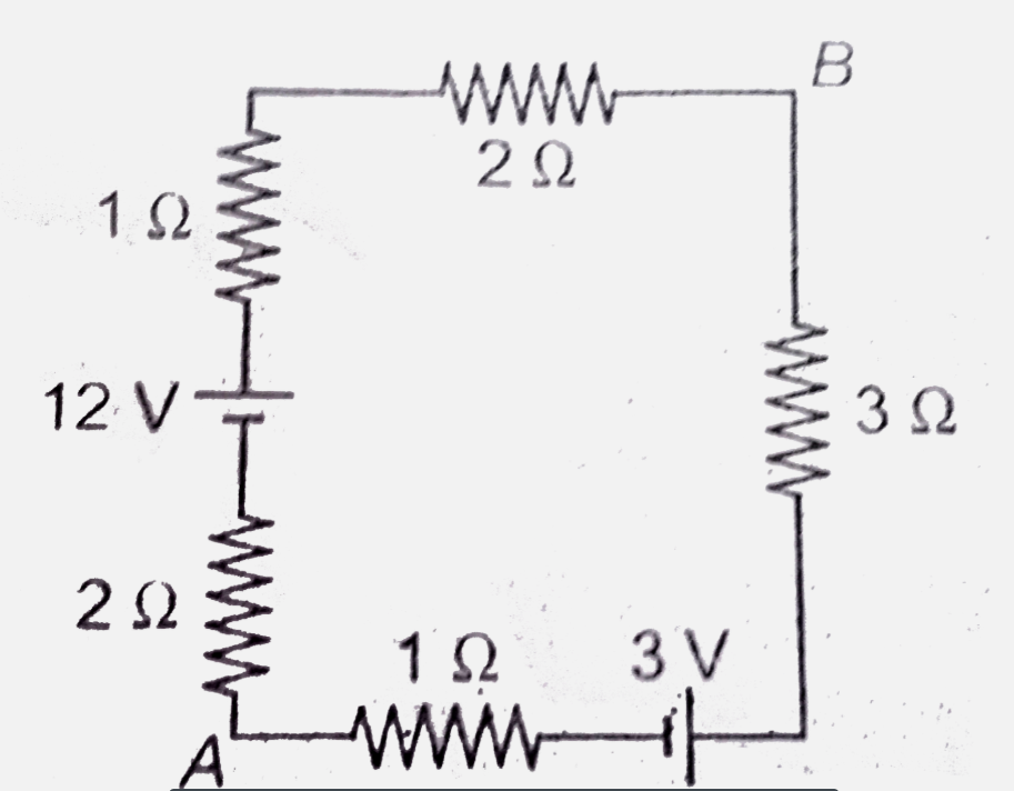
View SolutionPotentail difference VA−VB in the network shown in
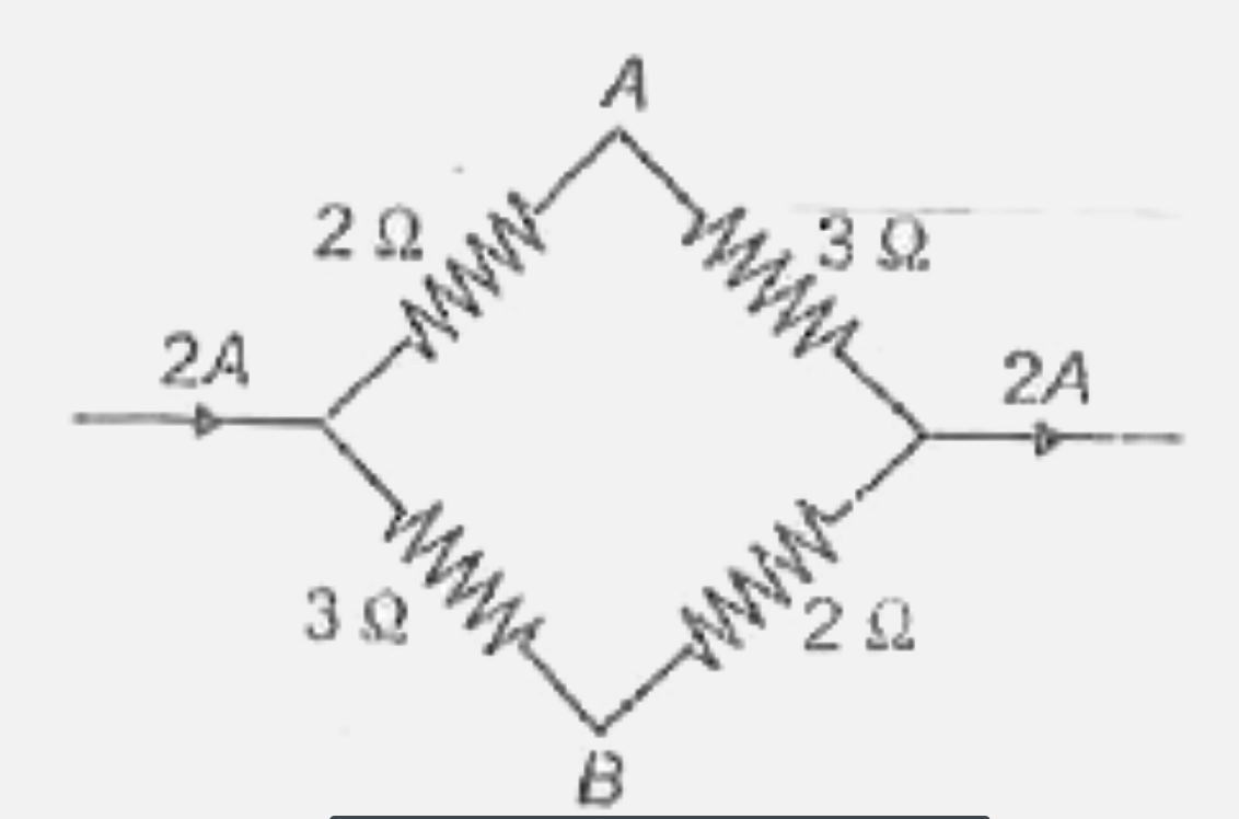
View SolutionPotential difference VB−VA in the network shown is
View SolutionIn uniform electric field, E=10NC−1 as shown in figure, find
(i) VA−VB
(ii) VB−VC.
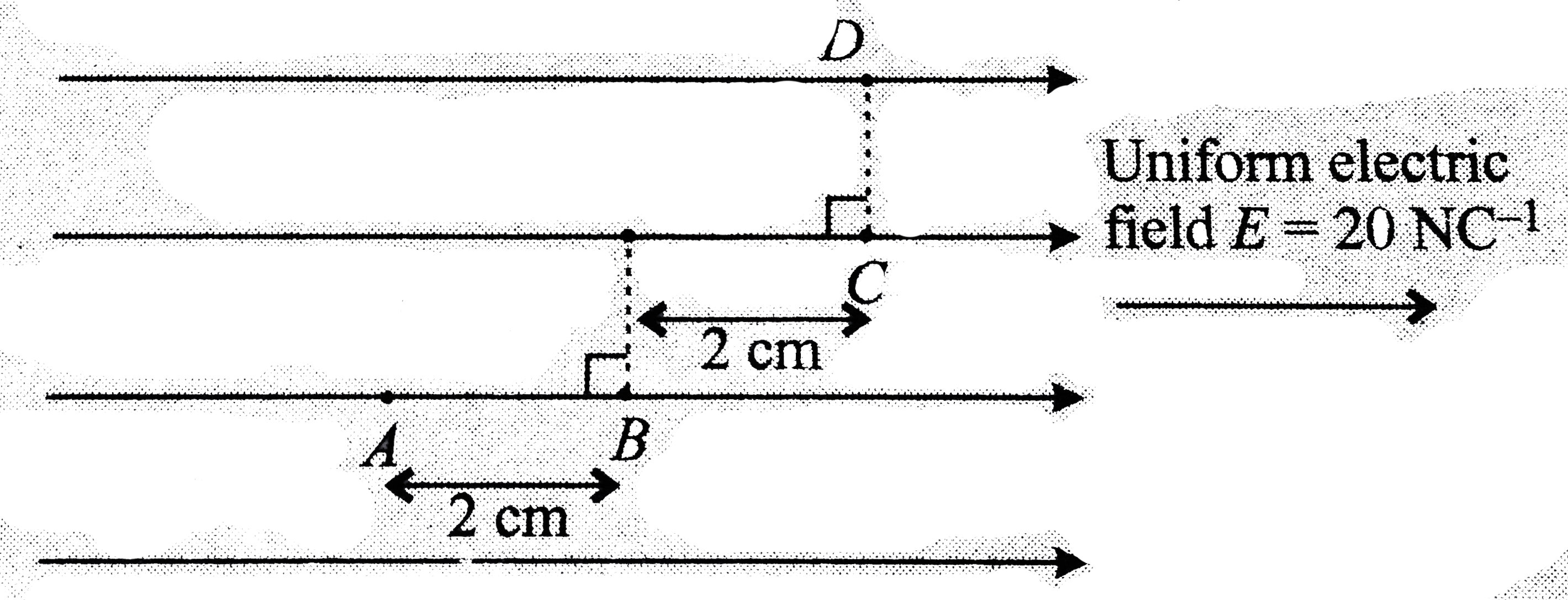
View SolutionFind out the following
a. VA−VB
b. VB−VC
c. VC−VA
d. VD−VC
e. VA−VD
f. Arrange the order of potential for points (A, B,C and D).
 .
.
View Solution