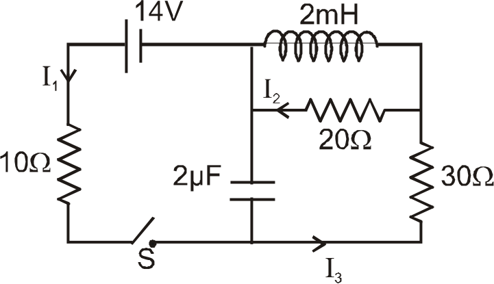
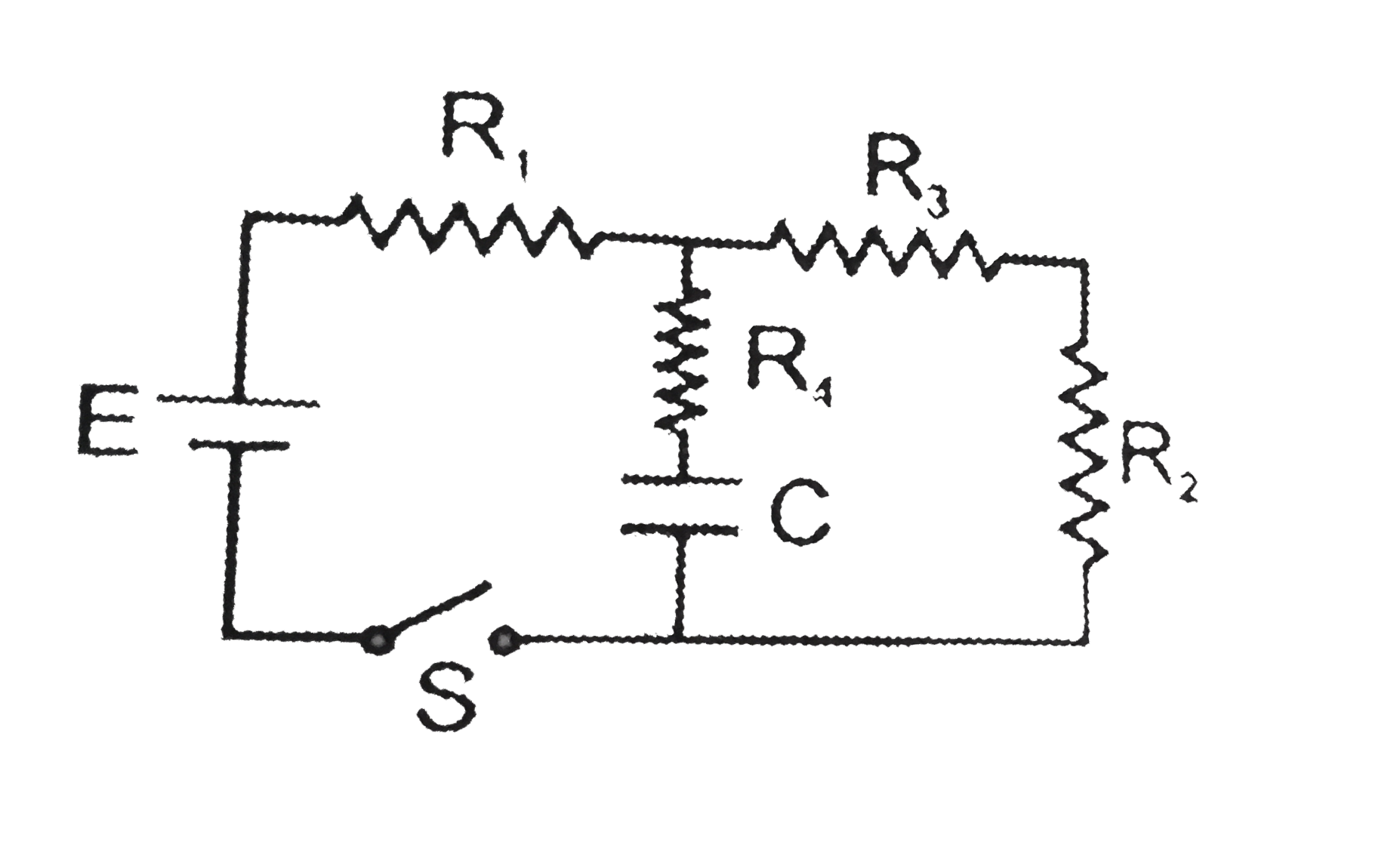
In the circuit shwon in fig. switch S is closed at time t = 0. Let I1andI2 be the currents at any finite time t, then the ratio I1/I2
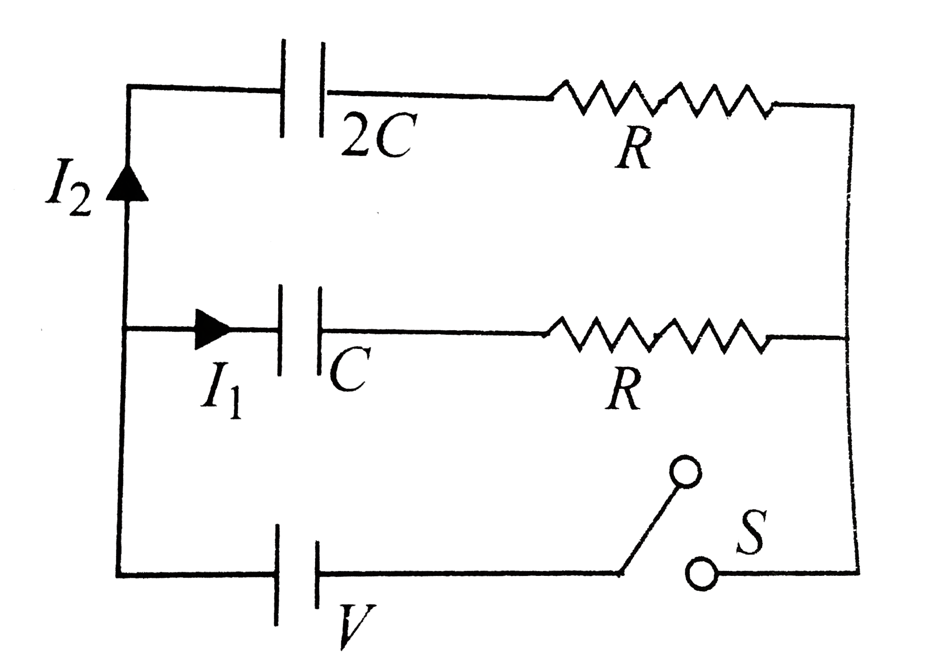
is constant
increases with time
decreases with time
first increases, then decreases
The correct Answer is:C
I=I0e−t/RCorI02=I0e−t/RCort=RC∈2
or 10−6×In4=(2+r)×0.5×10⁻⁶In2
Solving to get r=2Ω
Topper's Solved these Questions
- ELECTRIC CURRENT AND CIRCUITBOOK - CENGAGE PHYSICS ENGLISHCHAPTER - ELECTRIC CURRENT AND CIRCUITEXERCISE - Multiple Correct
16 Videos
- ELECTRIC CURRENT AND CIRCUITBOOK - CENGAGE PHYSICS ENGLISHCHAPTER - ELECTRIC CURRENT AND CIRCUITEXERCISE - Comprehension
35 Videos
- ELECTRIC CURRENT AND CIRCUITBOOK - CENGAGE PHYSICS ENGLISHCHAPTER - ELECTRIC CURRENT AND CIRCUITEXERCISE - Subjective
29 Videos
- ELECTRIC CURRENT & CIRCUITSBOOK - CENGAGE PHYSICS ENGLISHCHAPTER - ELECTRIC CURRENT & CIRCUITSEXERCISE - Kirchhoff s law and simple circuits
15 Videos
- ELECTRIC FLUX AND GAUSS LAWBOOK - CENGAGE PHYSICS ENGLISHCHAPTER - ELECTRIC FLUX AND GAUSS LAWEXERCISE - MCQ s
38 Videos
Similar Questions
In the circuit shown switch S is closed at t=0. Let i1 and i2 be the current at any finite time t then the ratio i1i2
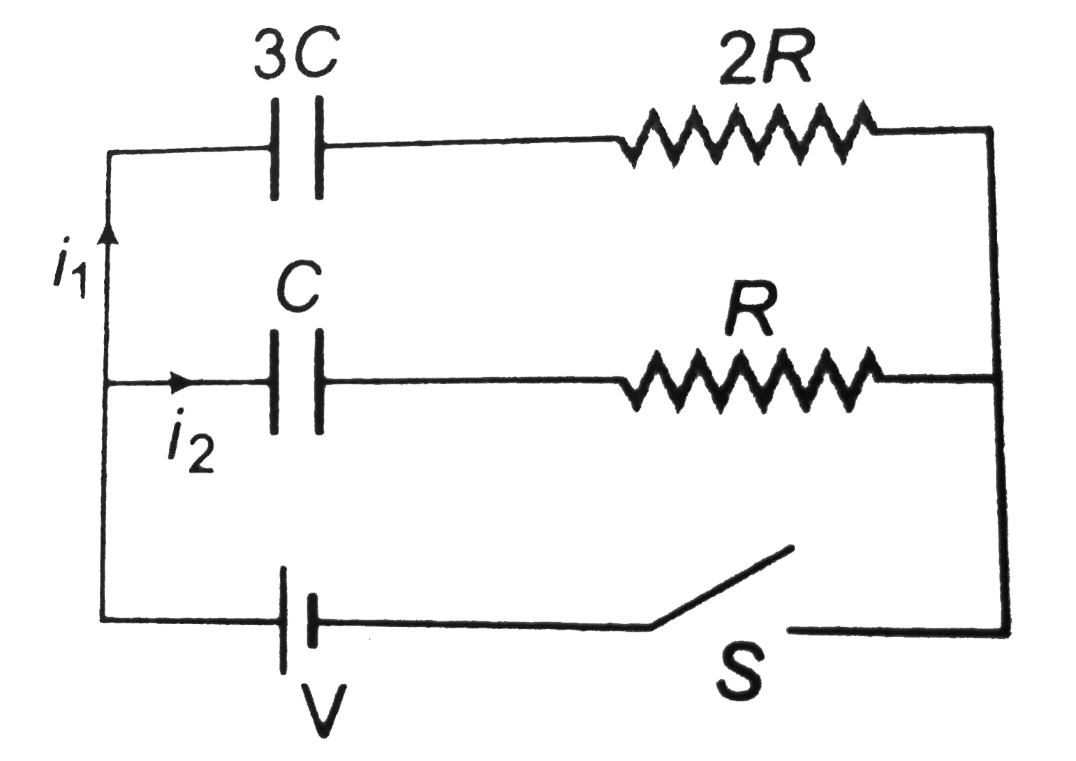
View SolutionIn the circuit shown, switch Sis closed att=O. Let i1andi2be the current at any finite time I, then the ratio i1/i2 is
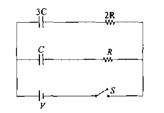
View Solution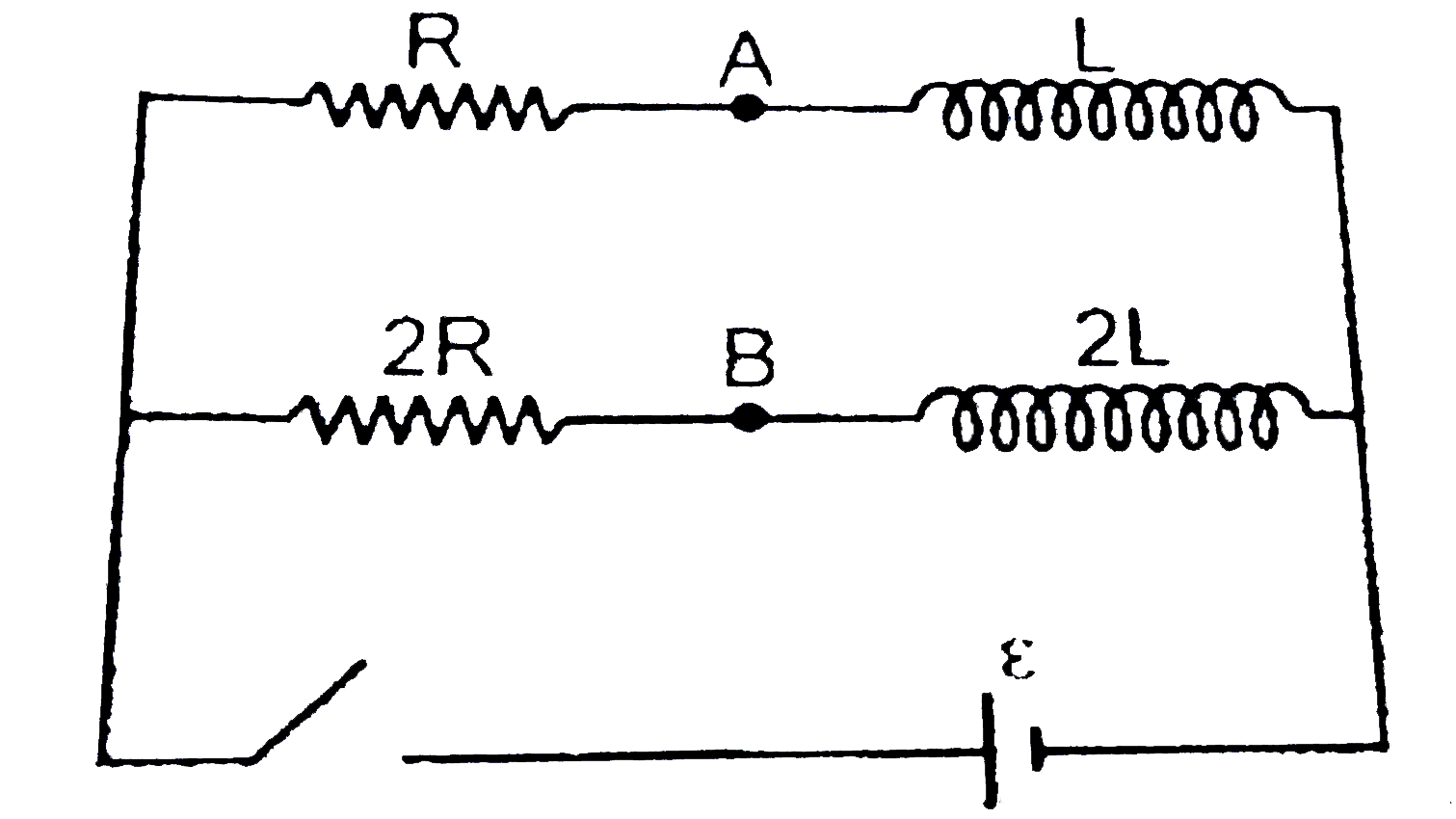
In given LR circuit the switch S is closed at time t=0 then
View SolutionIn the circuit shown, the switch is closed at t=0, the currents I1,I2 and I3 are
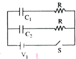
View SolutionIn the circuit shown in figure C1=2C2, Switch S is closed at time t = 0, Let i1andi2 be the currents flowing through C1andC2 at any time t, then the ratio i1/i2
View SolutionIn the circuit shown in figure switch S is closed at time t=0
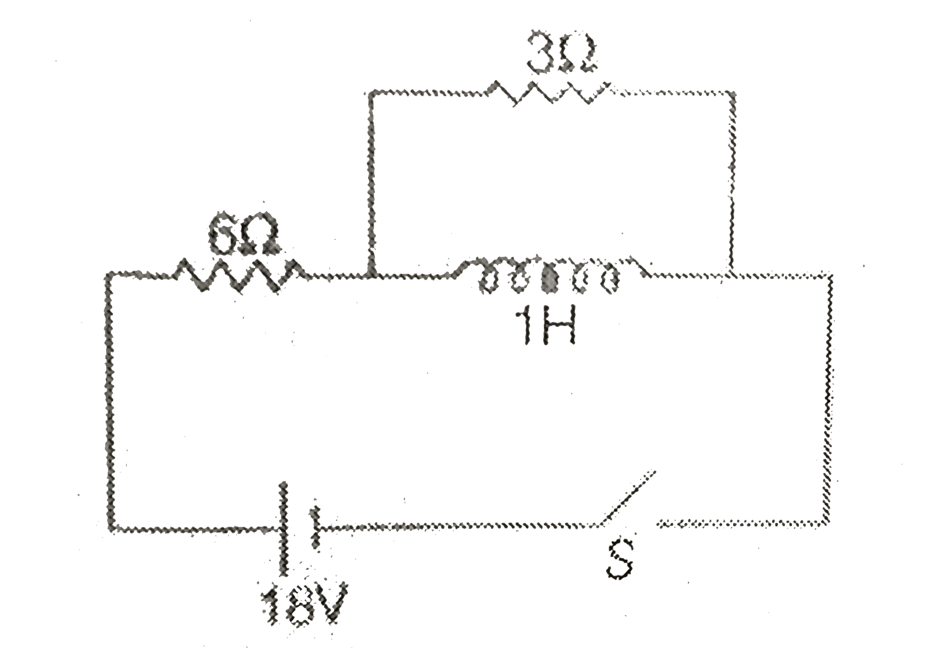
Current I from the battery at time t is given by
View SolutionIn the circuit shown, switch S is closed at time t=0. Find the current through the inductor as a function of time t.
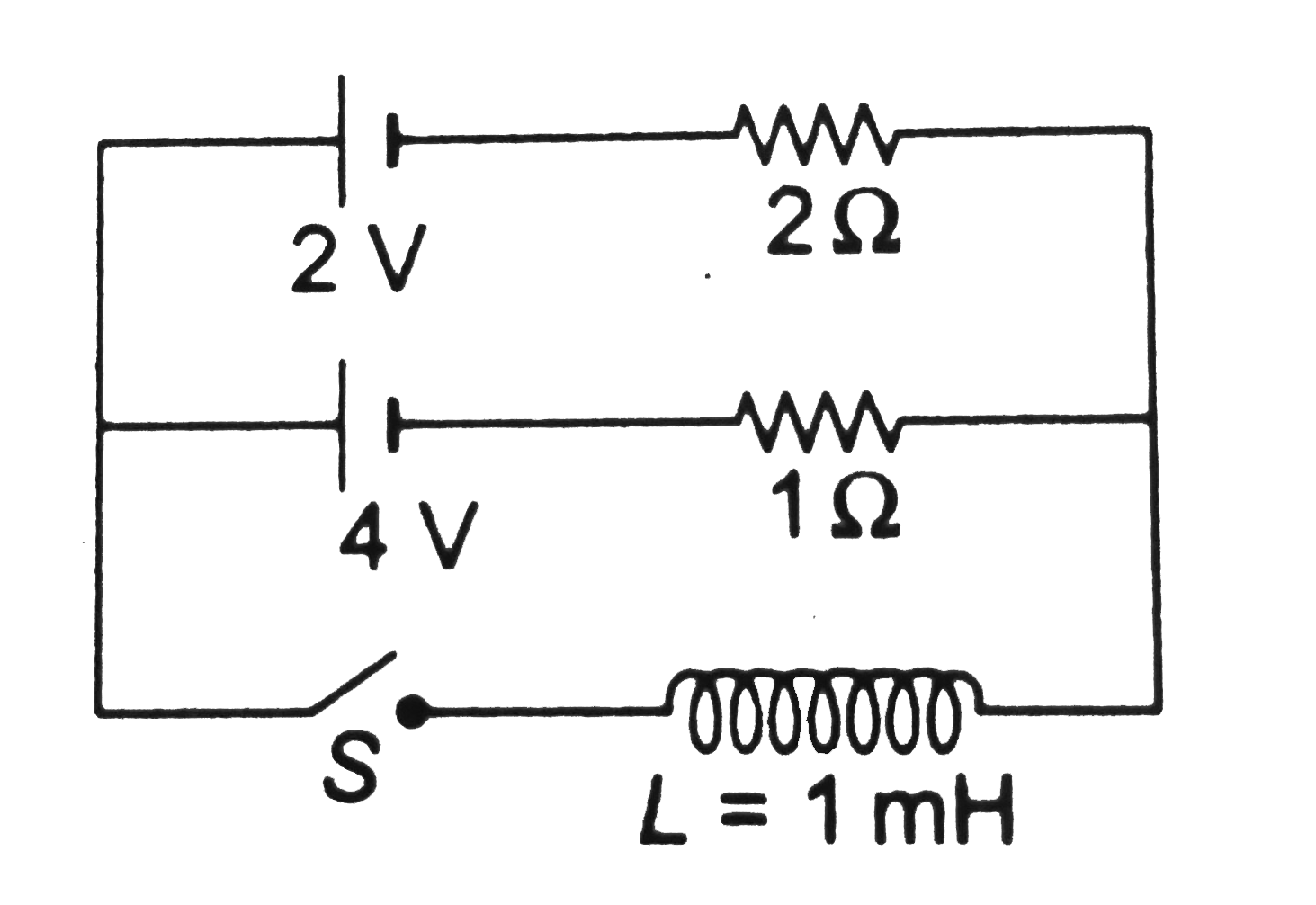
View SolutionIn the circuit shown in figure the switch S is closed at t = 0. A long time after closing the switch
View SolutionIn the circuit shown in fig., the value of I1+I2 is
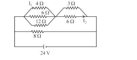
View SolutionIn the circuit shown in fig., the value of I1+I2 is

View Solution
