In the circuit shown if figure, XY is potentiometer wire 100cm long. The circuit is connected as shown. With switches S2 and S3 open, a balance point is found at Z. After switched S1 has remaind closed for some time, it is found that contact at Z must be moved towards Y to maintain a balance. which of the following in most likely reason for this ?
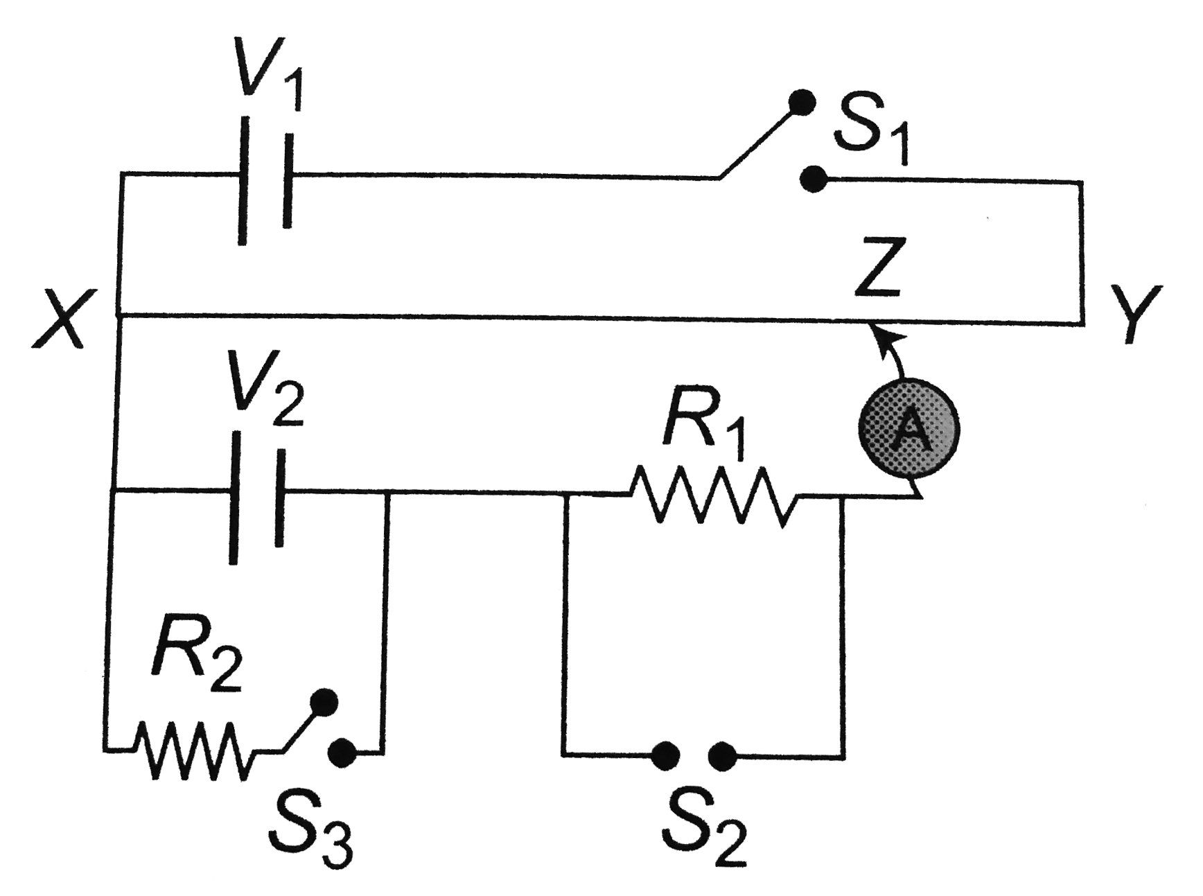
The cell V1 is running down
The cell V2 is running down.
The wire XZ is getting warm and its resistance is increasing.
The resistor R1 is getting warm and increasing in value.
The correct Answer is:A
a. If V1decreases, the potential difference across xz will decrease. So to have potential difference, i.e. , V2 across xz, length xz has to be increased or z should be moved toward y.
b. is incorrect because for this , z should have been moved toward x.
c. will be incorrect because xz can get warm up if current through it increases which is not possible .
d. is incorrect because there is no current in R1 .
Similar Questions
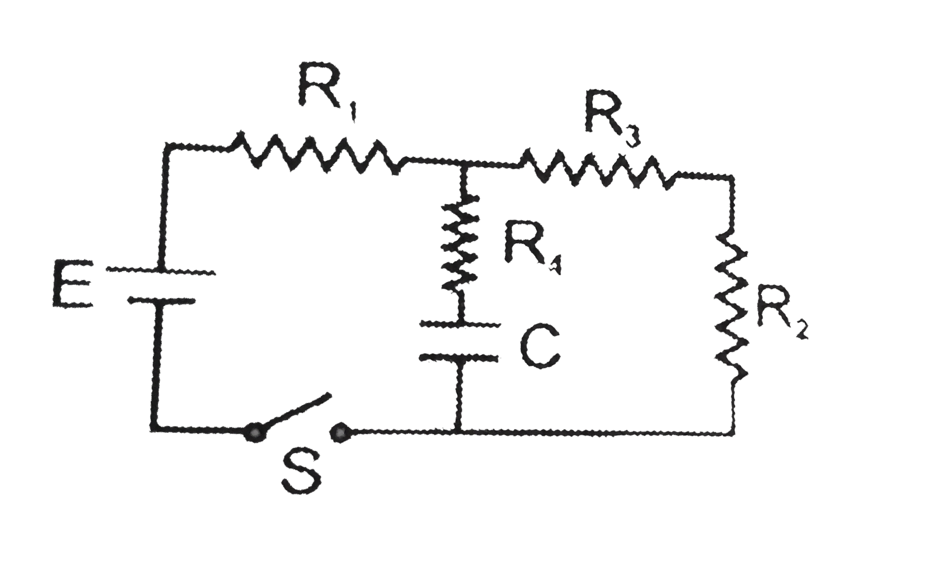
In the circuit shown in figure the switch S is closed at t = 0. A long time after closing the switch
 View Solution
In the circuit shown in the figure The steady state currents i1andi2 in the coils after the switch S is closed are
 View Solution
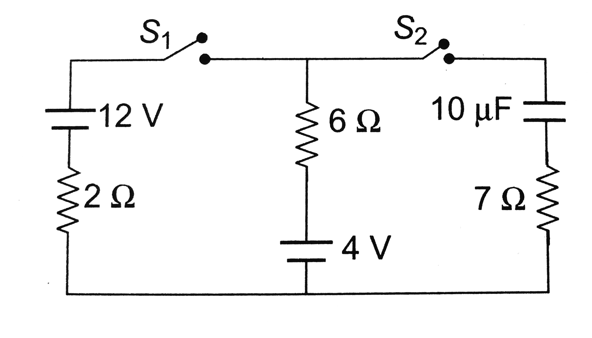
In the circuit shown in the figure, if switches S1 and S2 have been closed for a long time, then charge on the capacitor.
 View Solution
Consider the circuit shown in figure. The current through the battery a long time after the switch S is closed is:
 View Solution
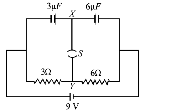
A circuit is connected as shown in the figure with the switch S open. When the switch is closed, the total amount of charge that flows from Y to X is
 . View Solution
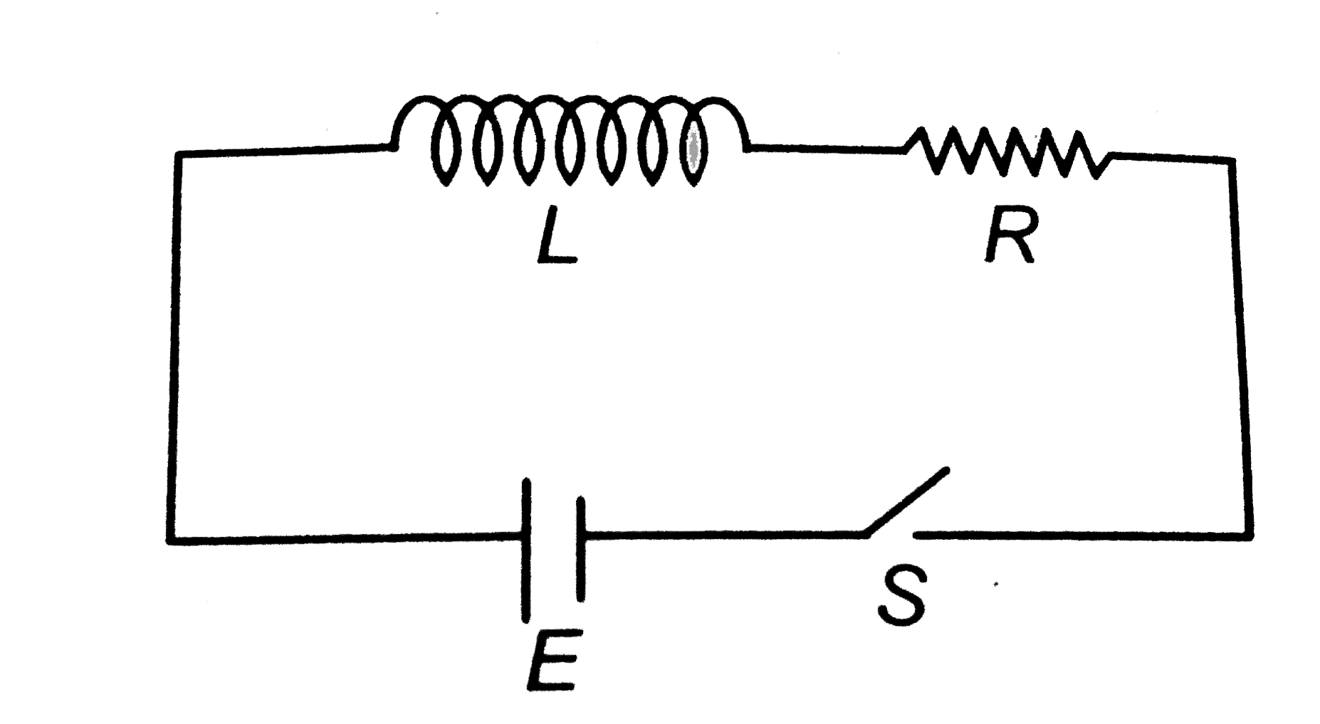
In the circuit shown in figure switch S is closed at time t=0. The charge which passes through the battery in one time constant is
 View Solution
In the circuit shown in figure switch S is closed at time t=0
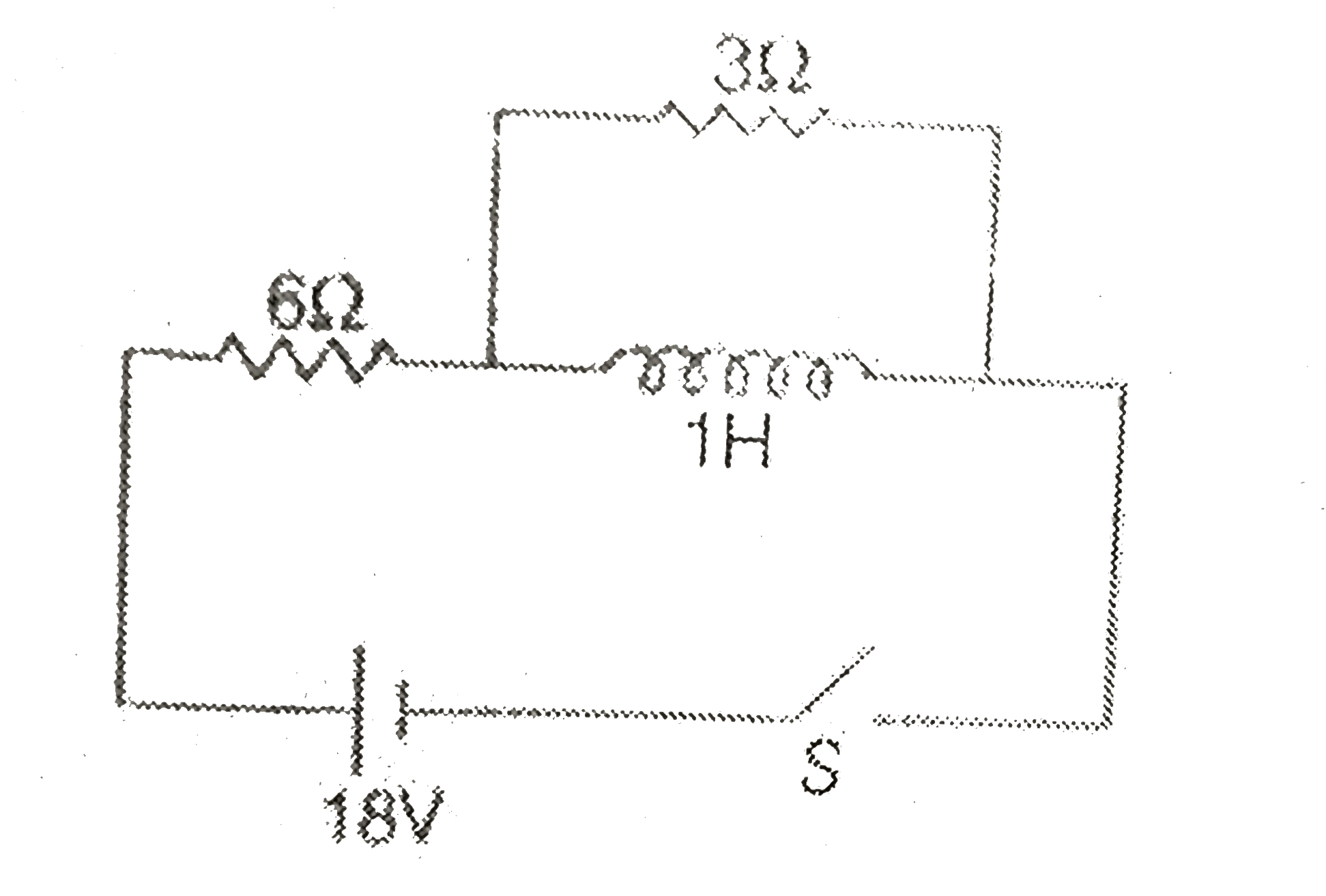
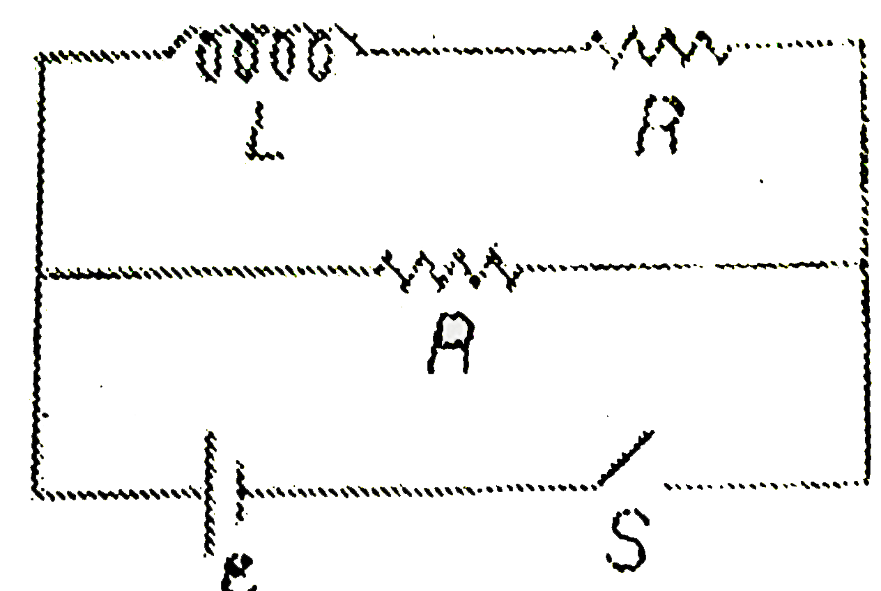
Potential difference across 3Ω resistance at time t is given byView SolutionIn the circuit shown in figure switch S is closed at time t=0, which statement is true after one time constant of L-R circuit?
 View Solution
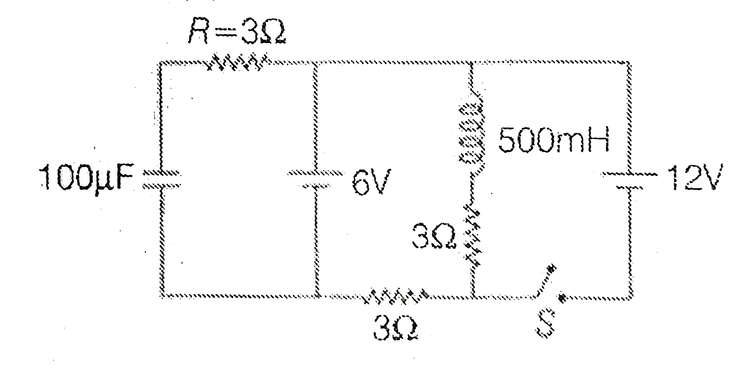
In the circuit diagram shown in figure, initially switch S is opened and the circuit is in steady state. At time t=0, the switch S is closed and the new steady state is reached after some time. Choose the correct option(s)
 View Solution
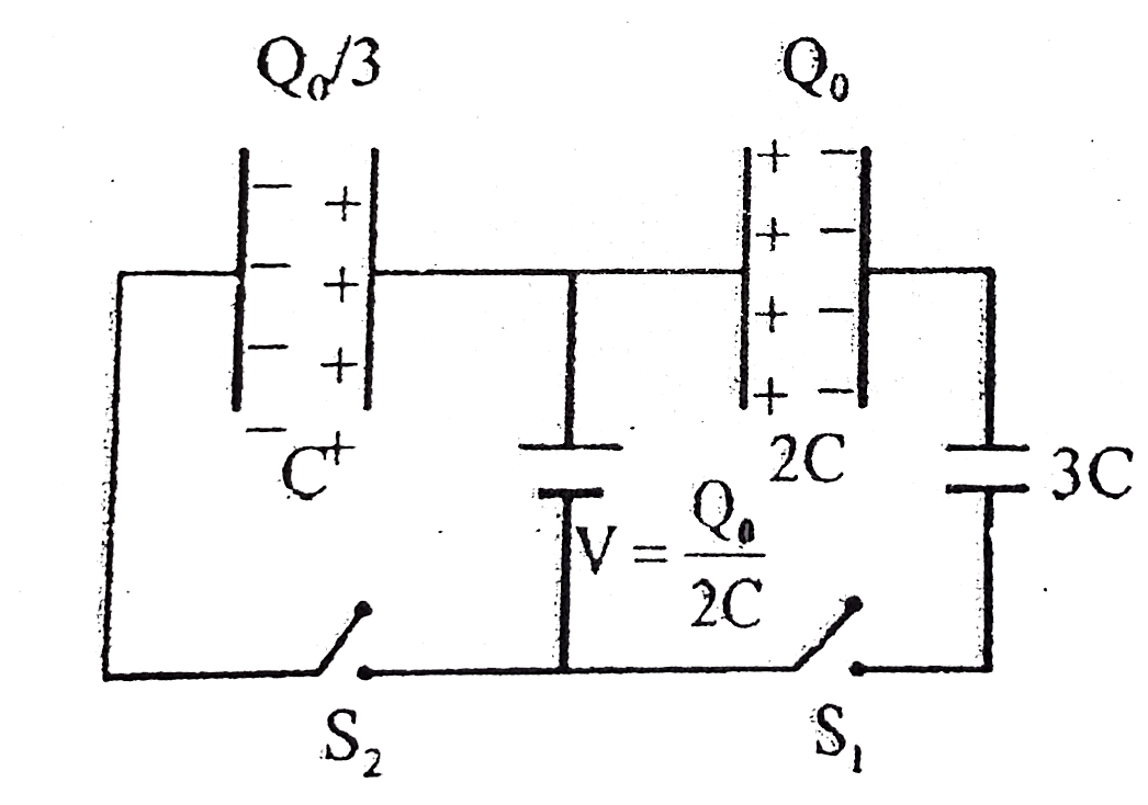
In the given circuit, the initial charges on the capacitors are shown in the figure. The charge flown through the switches S1andS2 respectively after closing the switches are
 View Solution

