A pair of parallel conducting rails lie at right angle to a uniform magnetic field of 2.0T as shown in the fig. two resistor 10Ω and 5Ω are to slide without friction along the rail. The distance between the conducting rails is 0.1m. Then
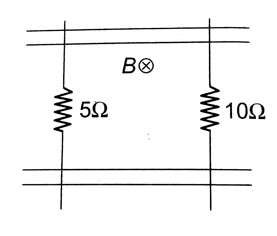
Induced current = 1150 A directed clockwise if 10Ω resistor is pulled to the right with speed 0.5ms−1 and 5Ω resistor is held fixed
Induced current 1300 A directed anticlockwise if 10Ω resistor is pulled to the right with speed 0.5ms−1 and 5Ω resistor is held fixed
Induced current 1300 A directed anticlockwise if 5Ω resistor is pulled to the left at 0.5ms−1 and 10Ω resistor is held at rest
Induced current 1150 A directed anticlockwise if 5Ω resistor is pulled to the left at 0.5ms−1 and 10Ω resistor is held at rest.
The correct Answer is:d
Step by step video & image solution for A pair of parallel conducting rails lie at right angle to a uniform magnetic field of 2.0T as shown in the fig. two resistor 10Omega and 5Omega are to slide without friction along the rail. The distance between the conducting rails is 0.1m. Then by Physics experts to help you in doubts & scoring excellent marks in Class 12 exams.
Updated on:21/07/2023Topper's Solved these Questions
- ELECTROMAGNETIC INDUCTIONBOOK - CENGAGE PHYSICS ENGLISHCHAPTER - ELECTROMAGNETIC INDUCTIONEXERCISE - comprehensive type
7 Videos
- ELECTROMAGNETIC INDUCTIONBOOK - CENGAGE PHYSICS ENGLISHCHAPTER - ELECTROMAGNETIC INDUCTIONEXERCISE - single correct answer
3 Videos
- ELECTROMAGNETIC INDUCTIONBOOK - CENGAGE PHYSICS ENGLISHCHAPTER - ELECTROMAGNETIC INDUCTIONEXERCISE - comprehensive
5 Videos
- ELECTRICAL MEASURING INSTRUMENTSBOOK - CENGAGE PHYSICS ENGLISHCHAPTER - ELECTRICAL MEASURING INSTRUMENTSEXERCISE - M.C.Q
2 Videos
- ELECTRON,PHONTS,PHOTOELECTRIC EFFECT & X-RAYSBOOK - CENGAGE PHYSICS ENGLISHCHAPTER - ELECTRON,PHONTS,PHOTOELECTRIC EFFECT & X-RAYSEXERCISE - dpp 3.3
15 Videos
Similar Questions
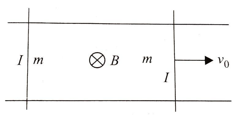
Consider parallel conducting rails separated by a distance l. There exists a uniform magnetic field B perpendicular to the plane of the rails as shown in Fig. Two conducting wires each of length l are placed so as to slide on parallel conducting rails. One of the wires is given a velocity v0 parallel to the rails. Till steady state is achieved, loss in kinetic energy of the system is
View SolutionA conducting rod of length is moved at constant velocity v0 on two parallel, conducting, smooth, fixed rails, that are placed in a uniform constant magnetic field B perpendicular to the plane for the rails as shown in Fig. A resistance R is connected between the two ends of the rails.
Then which of the following is/are correct:

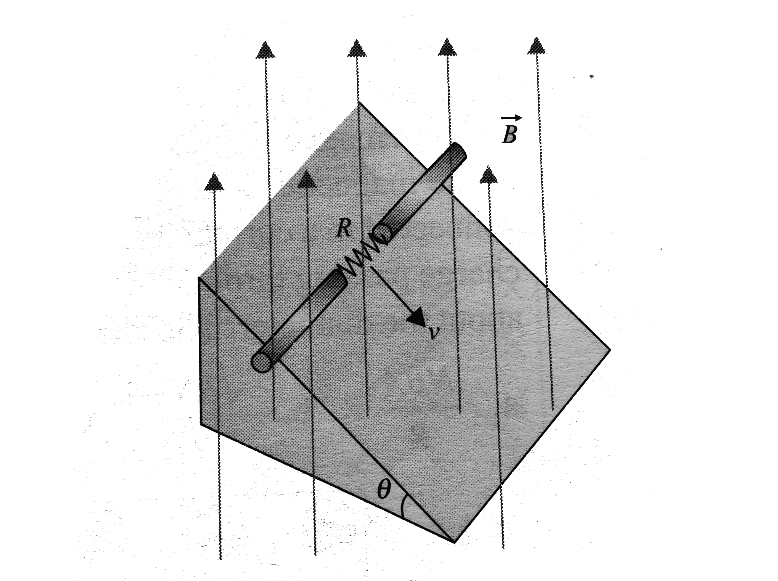
View SolutionA wire of length l, mass m and resistance R slides without any friction down the parallel conducting rails of negligible resistance . The rails are connected to each other at the bottom by a resistanceless rail parallel to the wire so that the wire and the rails form a closed rectangualr conducting loop. The plane of the rails makes an angle θ with the horizontal and a uniform vertical magnetic field of the inducetion B exists throughout the rregion. Find the steady state velocity of the wire.
View SolutionA conducting rod of length l slides at constant velocity v on two parallel conducting rails, placed in a uniform and constant magnetic field B perpendicular to the plane of the rails as shown in Fig.3.49. A resistance R is connected between the two ends of the rails.
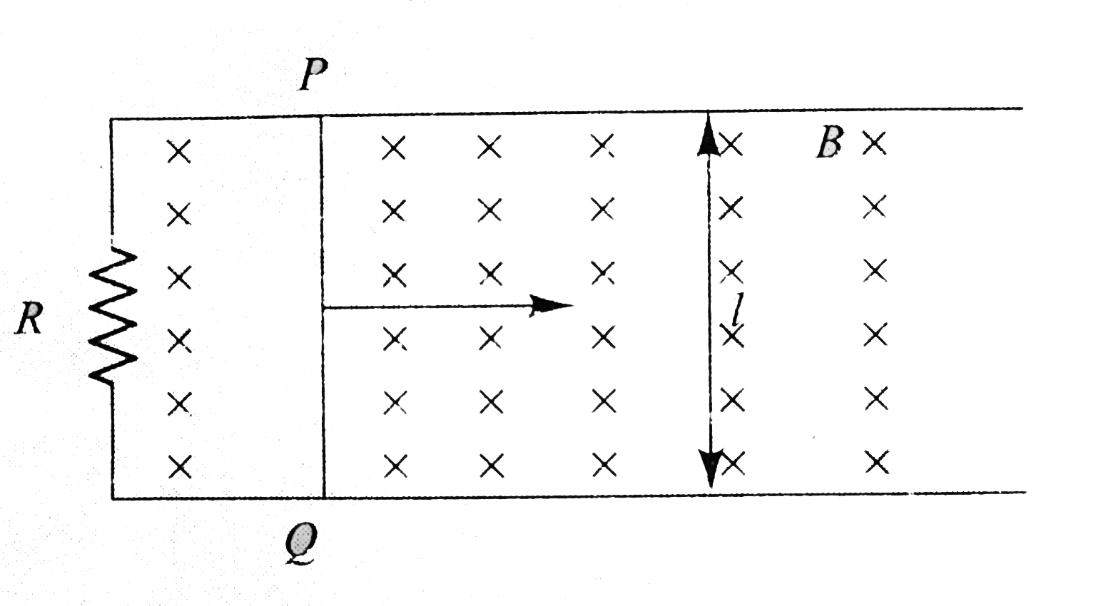
(a) Idenify the cause which produces change in magnetic flux.
(b) Identify the direction of current in the loop.
( c) Determine the emf induced in the loop.
(d) Compute the electric power dissipated in the resistor.
(e) Calcualte the mechenical power required to pull the rod at a cinstant velovity.
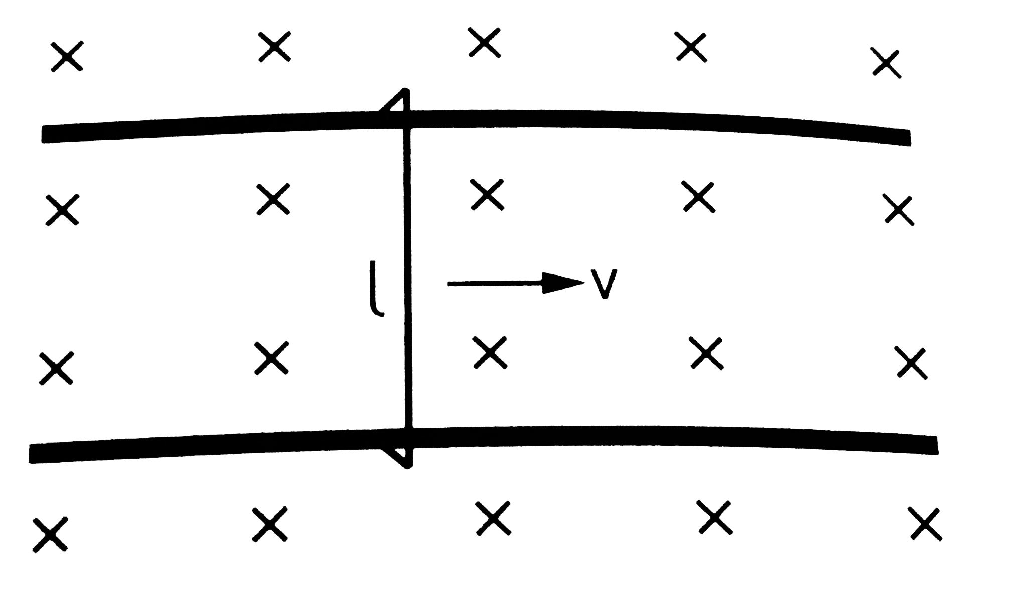
View SolutionShows a wire sliding on two parallel, conducting rails placed at a separaton l. A magnetic feld B exists in a direction perpendicular to the plane of the rails. What force is necessary to keep the wire moving at a constatn velocity v ?
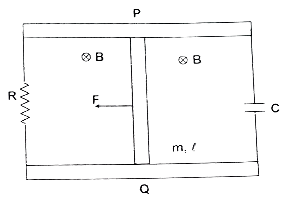
View SolutionTwo smooth horizontal parallel conducting rails are connected with a capacitor and a resistor at the two ends as shown. A uniform conducting rod PQ of mass 'm' and length 'l' is dragged with a constant horizontal force 'F'. The terminal velocity aquired by the conducting rod is
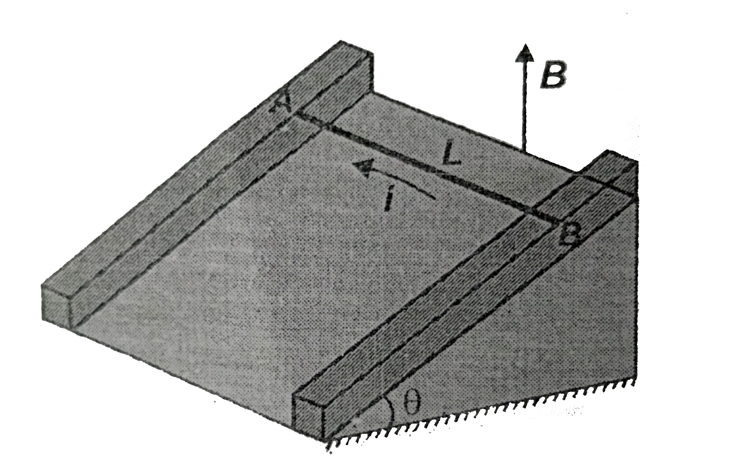
View SolutionOn an inclined plane, two conducting rails are fixed along the line of greatest slope. A conducting rod AB is placed on the radils so that it is horizontal. A vertically upward uniform magnetic field is present in the region. A current i flows through AB from B to A. The mass of AB is m and the coefficient of friction between the rod and rails is μ. Find the minimum and maximum value of B, so that the rod can stay in equilibrium. Assume that μ<tanθ
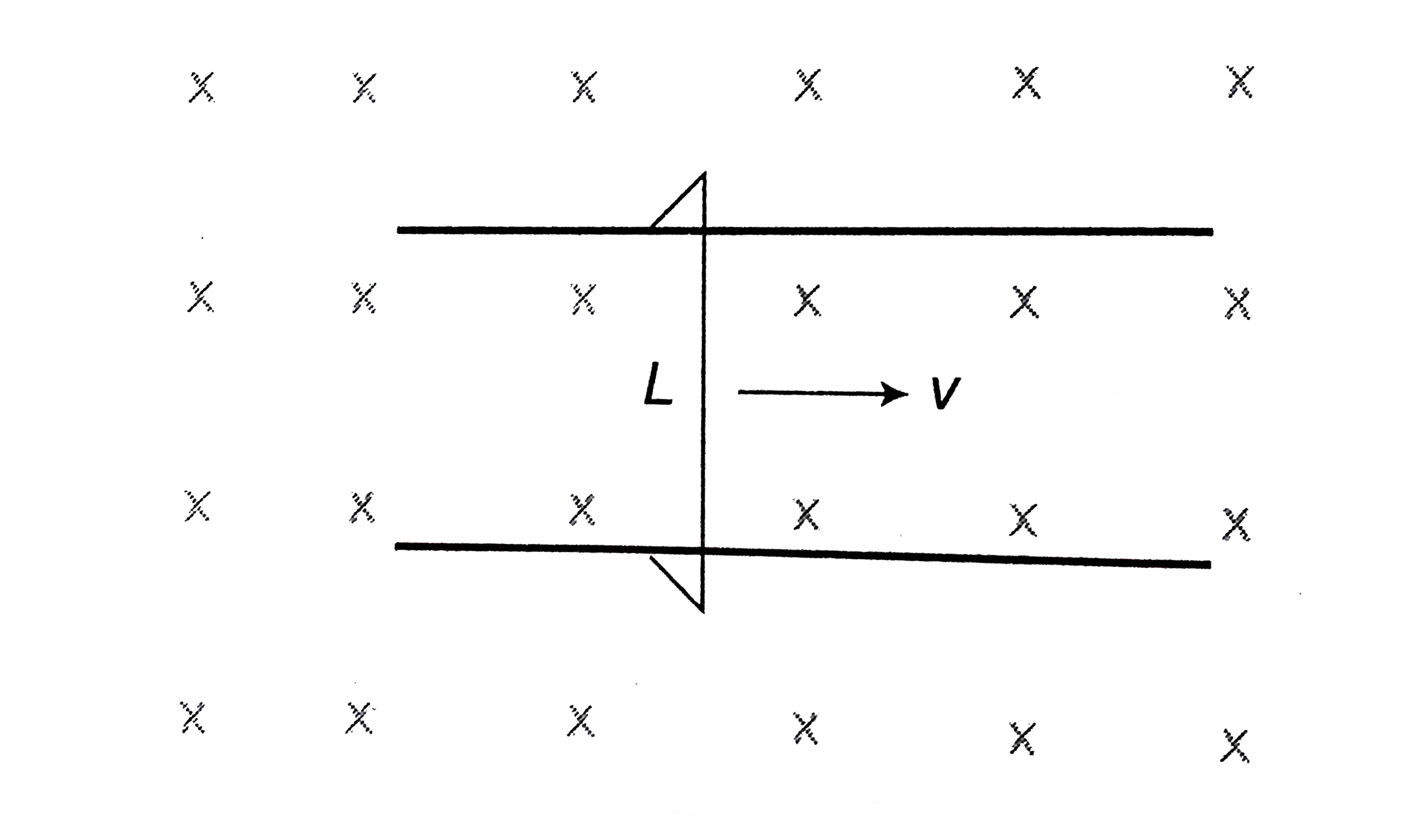
View SolutionFigure shows a wire sliding on two parallel, conducting rails placed at a separation L . A magnetic field B exists in a direction perpendicular to the plane of the rails. What force is necessary to keep the wire moving at a constant velocity V ?
View SolutionTwo long parallel conducting horizontal rails are connected by a conducting wire at one end. A uniform magnetic field B (directed vertically downwards) exists in the region of space.
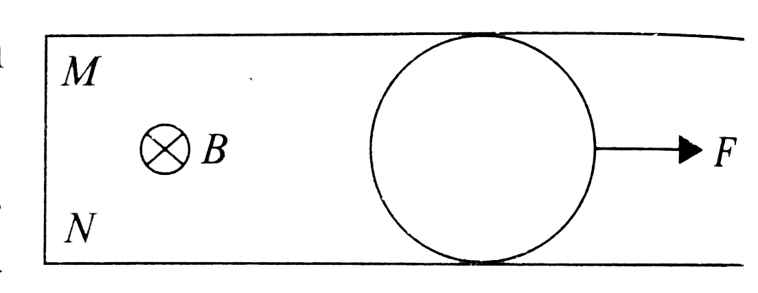
A light uniform ring of diameter d which is practically equal to separation between the rails is placed over the rails as shown in Fig. If resistance of ring be (λ) per unit length
The force required to pull the ring with uniform velocity v is
View Solution
