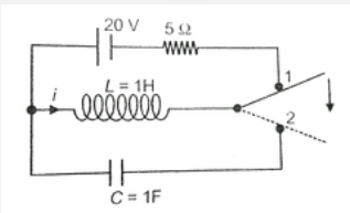
The switch in figure Iis connected to position a for a long time interval. At t=0, the switch is thrown to position b. After this time , what are

the frequency of oscillation of the LC circuit
the maximum charge that appears on the capacitor
the maximum current in the indictor
the total energy the circuit possesses at t=3.00 s

The correct Answer is:A
Step by step video & image solution for The switch in figure Iis connected to position a for a long time interval. At t = 0, the switch is thrown to position b. After this time , what are by Physics experts to help you in doubts & scoring excellent marks in Class 12 exams.
Updated on:21/07/2023Topper's Solved these Questions
- INDUCTANCEBOOK - CENGAGE PHYSICS ENGLISHCHAPTER - INDUCTANCEEXERCISE - Comprehension Type
8 Videos
- INDUCTANCEBOOK - CENGAGE PHYSICS ENGLISHCHAPTER - INDUCTANCEEXERCISE - Concept Based
8 Videos
- INDUCTANCEBOOK - CENGAGE PHYSICS ENGLISHCHAPTER - INDUCTANCEEXERCISE - Single correct Answer Type
22 Videos
- HEATING EFFECT OF CURRENTBOOK - CENGAGE PHYSICS ENGLISHCHAPTER - HEATING EFFECT OF CURRENTEXERCISE - Thermal Power in Resistance Connected in Circuit
27 Videos
- MAGNETIC FIELD AND MAGNETIC FORCESBOOK - CENGAGE PHYSICS ENGLISHCHAPTER - MAGNETIC FIELD AND MAGNETIC FORCESEXERCISE - Multiple Correct Answer type
2 Videos
Similar Questions
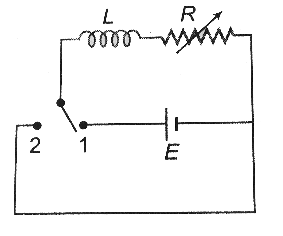
In the circuit shown in the figure initialy the switch in position 1 for a long time, then suddenly at t=0 the switch is shifted to position 2. It is required that a constant current should flow in the circuit, the value of resistance R in the circuit
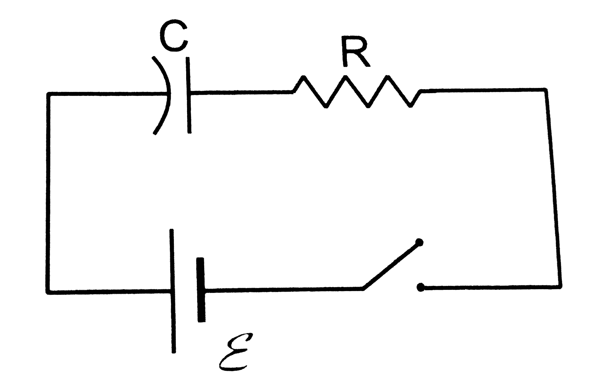
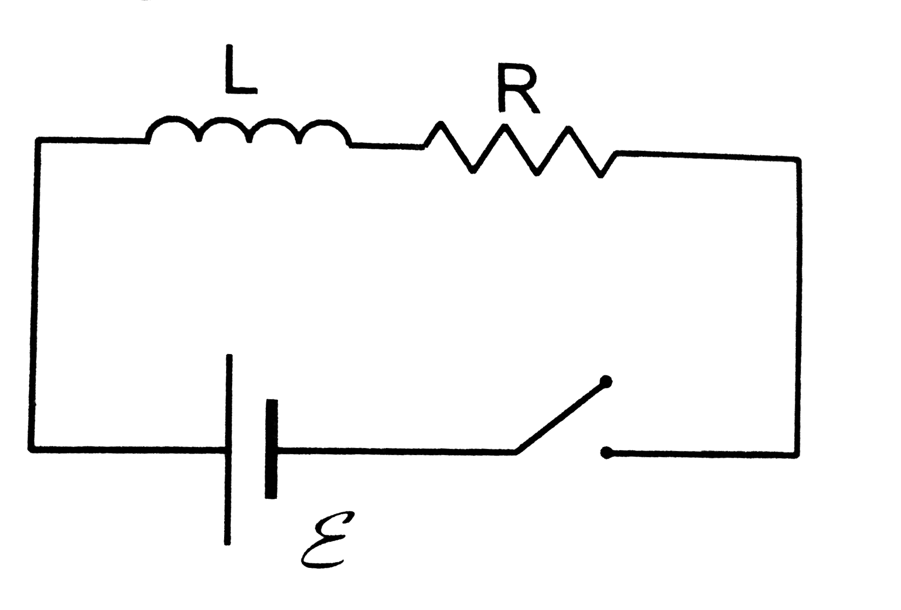
View SolutionThe switches in figure and are closed at =0 and reopended after a long time at t=t0.
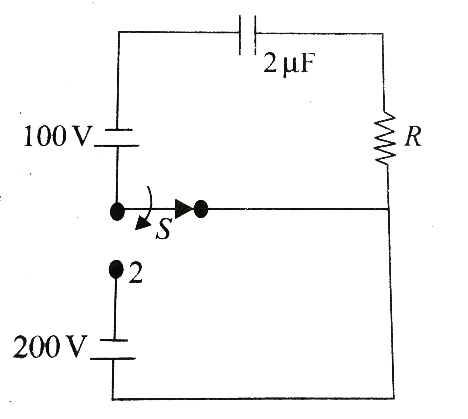
View SolutionIn the circuit shown below, the switch is in position 1 for a long time. At some moment after that the switch is thrown in position 2. The quantity of heat generated in the resistance of 375 ohm after the switch is changes to position 2 is :

View SolutionIn the circuit shown in the figure, the switch S is in position 1 for a long time. Now the switch is thrown to position 2. Find the total heat developed in the circuit till the steady state is reached again.
View SolutionThe switches in figure and are closed at =0 and reopended after al long time at t=t0.


View SolutionSwitch S of circuit shown in Fig 5.200 is in position 1 for a long time. At instant t = 0, it is thrown from position 1 ot 2 Calcuate thermal power P1(t)P2(t) generated across resistanace R1andR2, respectively.
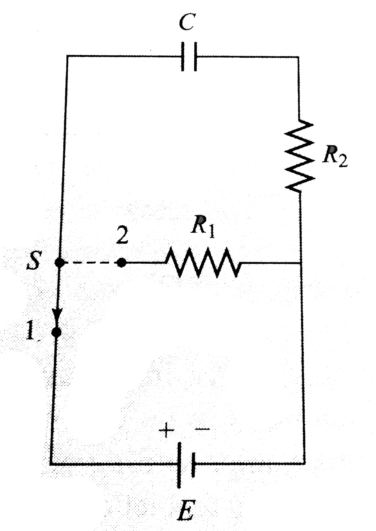
View SolutionIn the circuit shown, the switch has been in position 1 for a long time. Now the switch is shifted to position 2. If this instant is taken as t = 0, then at time t=π2
View SolutionIn Fig. switch S is closed for a long time. At t=0, if it is opened, then
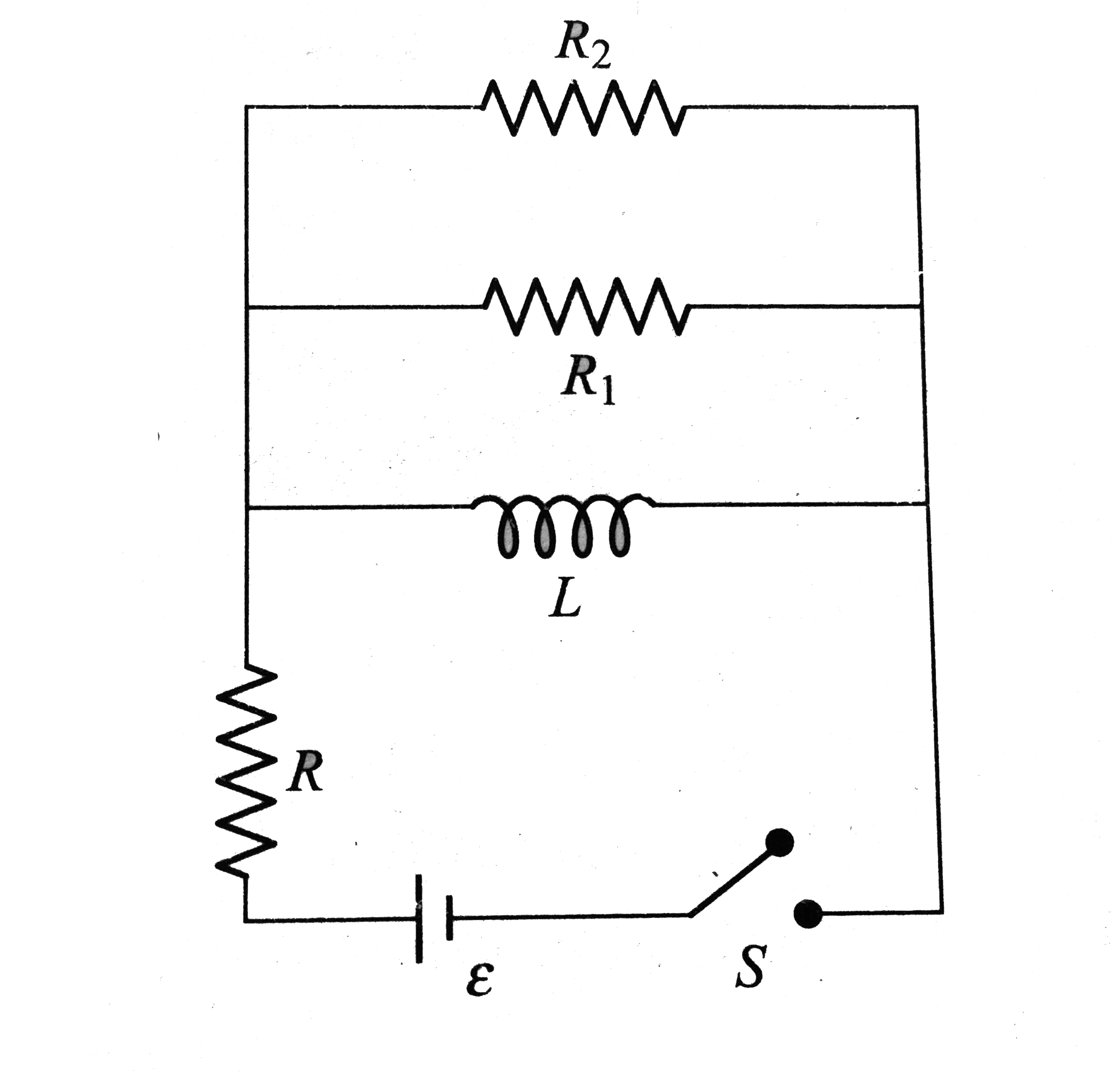
View SolutionIn Fig. switch S is closed for a long time. At t=0, if it is opened, then

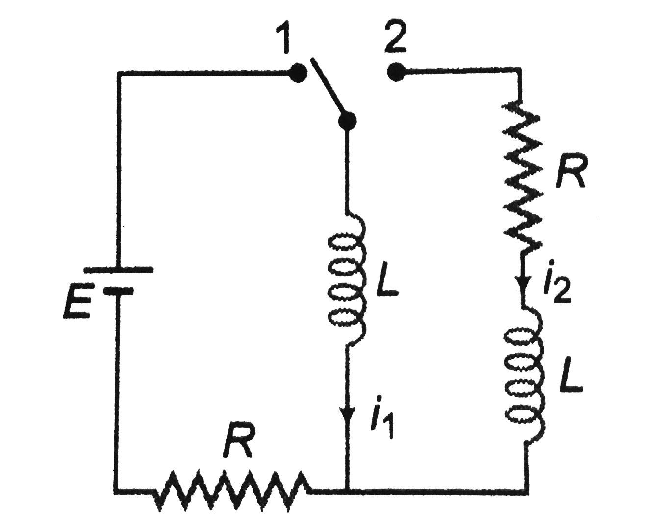
View SolutionIn figure, the switch is in the position 1 for long time, then the switch is shifted to position 2 at t=0. At this instant the value of i1 and i2 are
View Solution
