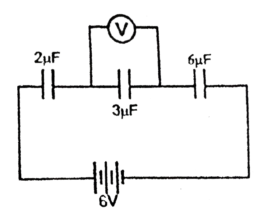
In the circuit shown in the figure, the voltmeter reading would be
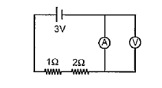
0 volt
0.5 volt
1 volt
2 volt
The correct Answer is:A
Similar Questions
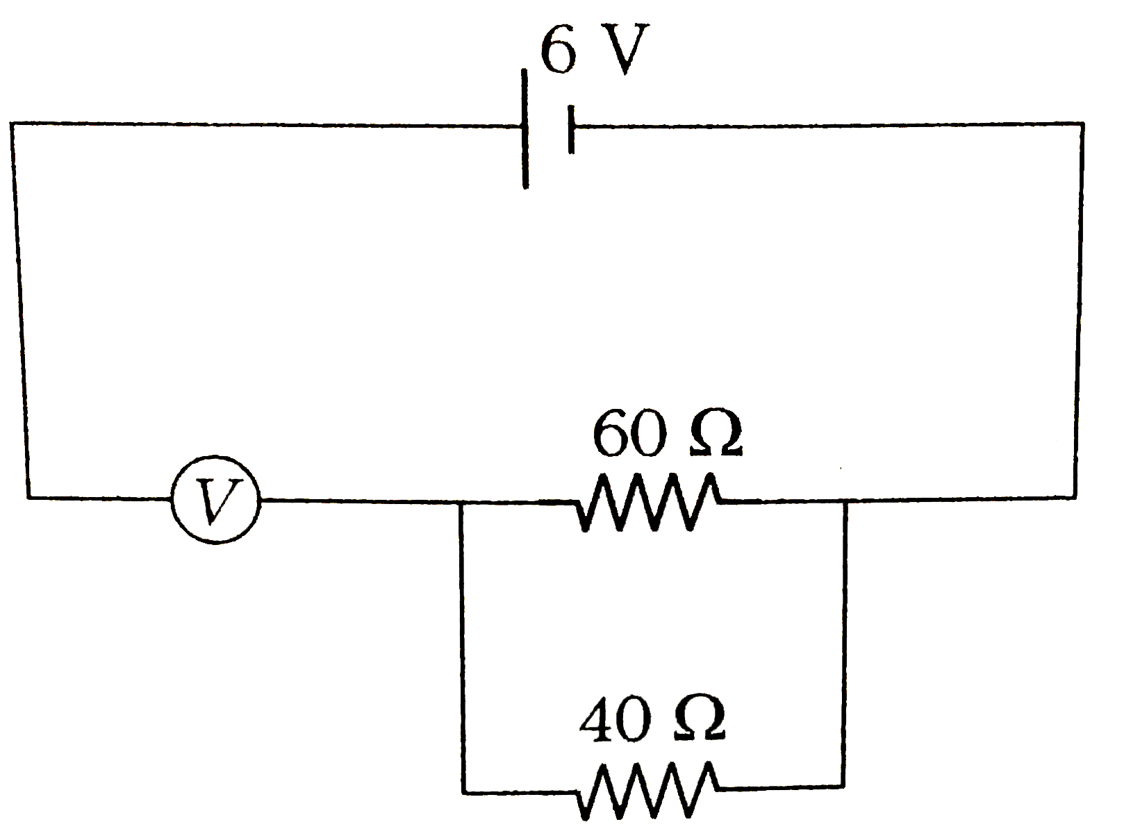
In the circuit shown in the figure, the voltmeter reading is
View SolutionState ohm's law.
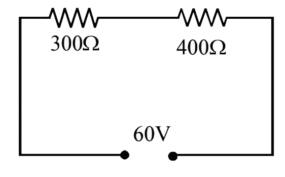
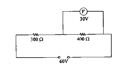
In the circuit shown in figure, a voltmeter reads 30 volts when it is connected across 400 ohm resistance. Calculate what the same voltmeter will read when it is connected across the 300 ohm resistance.
View Solution
Knowledge Check
In the circuit shown in the figure, the voltmeter reading is
 A2.4VB3.4VC4.0VD6.0V
In the series circuit shown in the figure the voltmeter reading will be (all the meters are ideal).
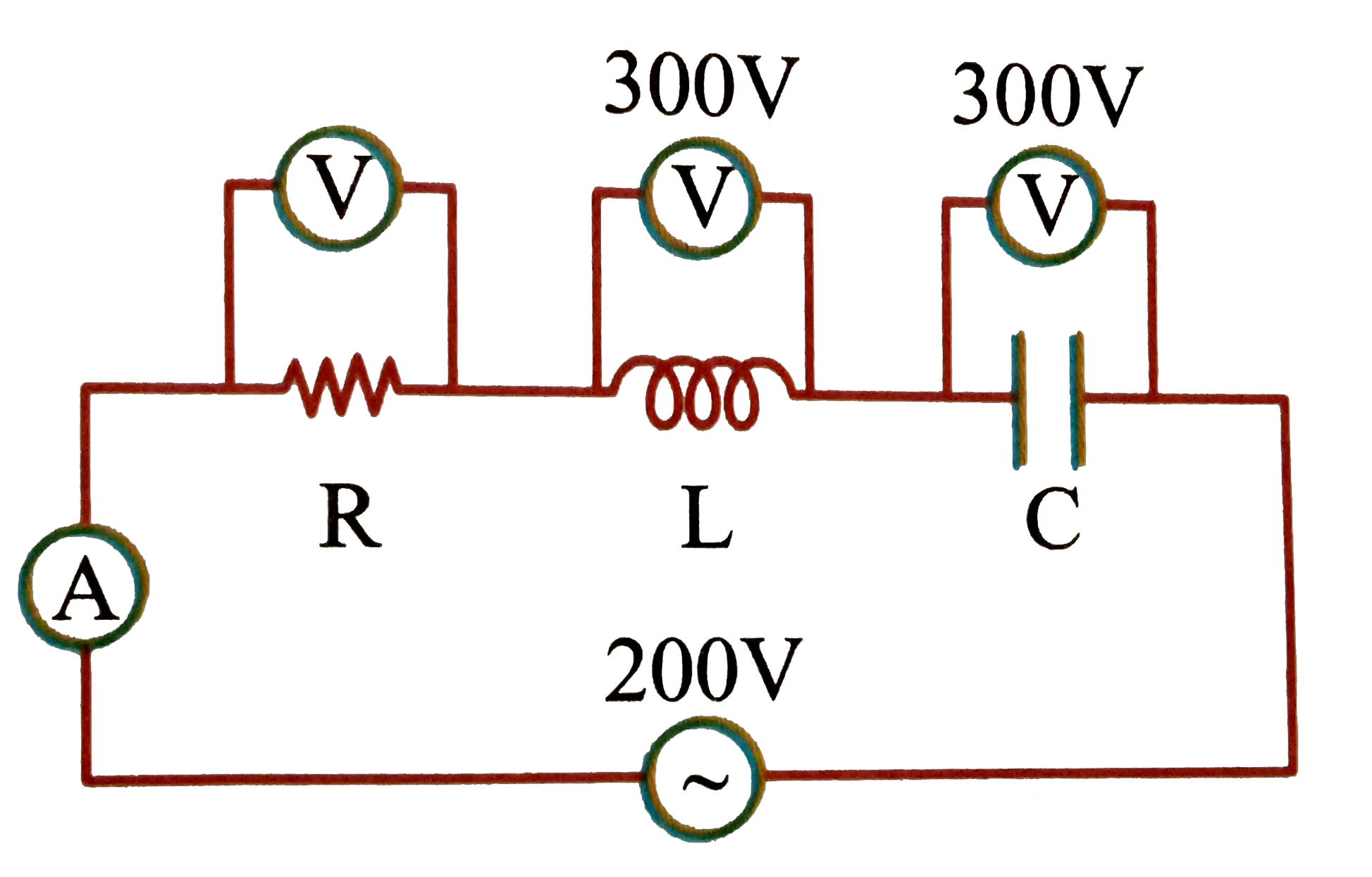 A300VB200VC100VD600V
Consider the two circuits A and B given alongside :
In the circuits A and B shown here, the voltmeter reading would be :
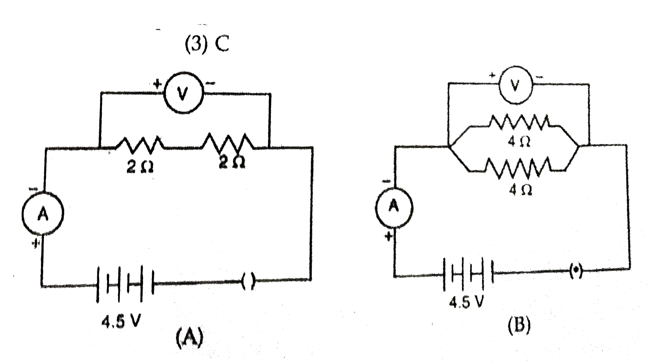 Anearly 4.5 V in both the circuitsB0 V in both the circuitsCnearly 1 V for circuit A and nearly 4.5 V for circuit B.D0 V for circuit A and nearly 4.5 V for circuit B.
In the circuit shown in figure-3.387, the voltmeter is having a resistance 4000Ω. Find the percentage error in reading of this voltmeter.
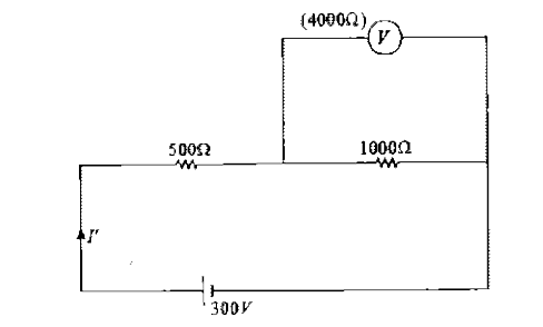
View SolutionIn the circuit shown in figure-3 .3 89, the voltmeter reads 30V when it is connected across 400Ω resistance. Calculate what the same voltmeter will read when it is connected across the 300Ω resistance.
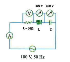
View SolutionIn the series LCR circuit as shown in the figure, the voltmeter V and ammeter A reading are
View SolutionIn the combination shown in the figure, the ideal voltmeter reading will be
View SolutionState ohm's law.
In the circuit shown in figure, a voltmeter reads 30 volts when it is connected across 400 ohm resistance. Calculate what the same voltmeter will read when it is connected across the 300 ohm resistance.

View Solution
