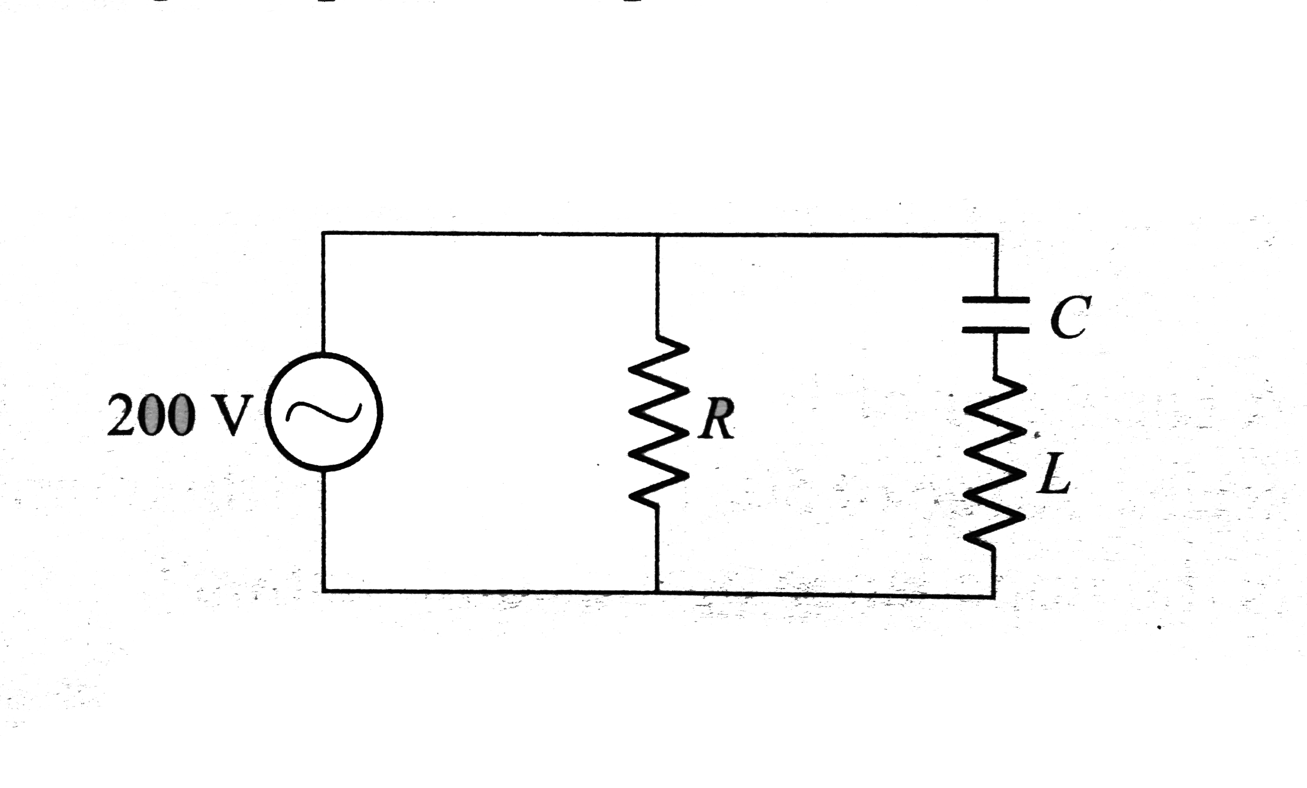
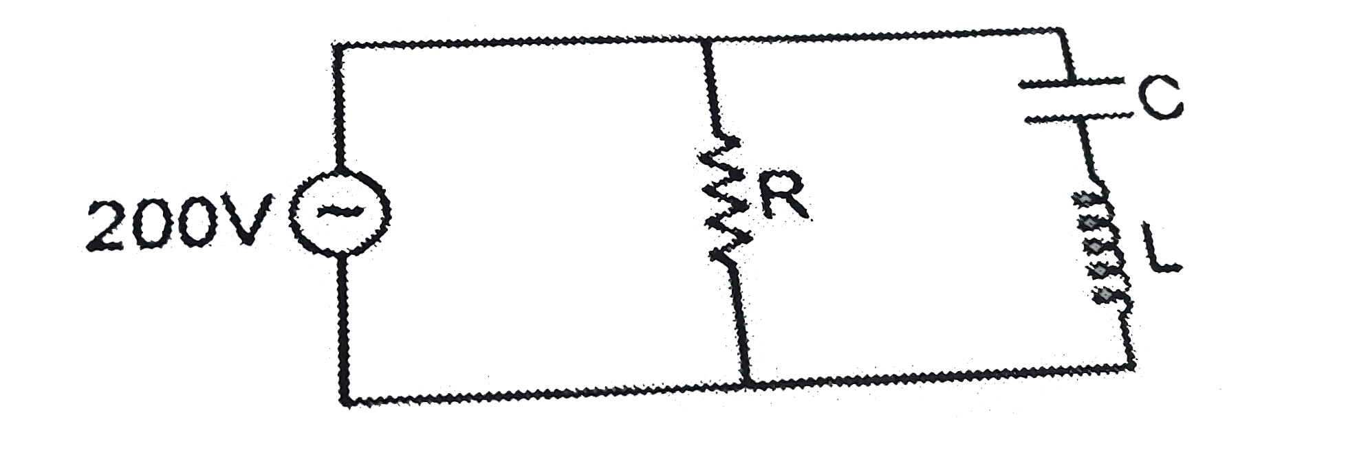
In the circuit điagram shown, and . The effective current throagh the source is ampere. Find .
'(##CEN_KSR_PHY_JEE_C24_E01_022_Q12##)'
The correct Answer is:4
Topper's Solved these Questions
Similar Questions
Knowledge Check
In the circuit shown in fig. XC=100Ω,(XL)=200ΩandR=100Ω. The effective current through the source is
 A2AB2√2AC0.5AD√0.4A
In the circuit diagram show, XC=100Ω,XL=200Ω,&R=100Ω
 A2AB2√2AC0.5AD√0.4A
In the circuit shown, find the value of current I (in ampere).
'(##CEN_KSR_PHY_JEE_CO20_E01_037_Q31##)'
View SolutionMaximum power loss (in watt) in the given circuit is
'(##CEN_KSR_PHY_JEE_C24_E01_020_Q10##)'
View SolutionFind the potential difference |leftVs−VAright| (in volt) between the plates of the capacitor C shown in the figure, if the sources have emfs E,=4V and E2=1V and the resistances are equal to R1=10ohm,R2=20ohm and R3=30ohm. The internal resistances of the sources are neglectable

View SolutionFind n, if the total power dissipated in the circuit is 6n watts.
'(##CEN_KSR_PHY_JEE_CO20_E01_034_Q28##)'
View SolutionIn the circuit shown, the batteries have emf E(t)=E2=1 (V),E3=2.5V and the resistance R1=10ohm,R2=20ohmCapacitance C=10μF. The magnitude of charge (in μC ) on the left plate of the capacitor C at steady state is
'(##CEN_KSR_PHY_JEE_CO20_E01_022_Q17##)'
View SolutionIn the shown figure, the focal length of equivalent system is 50x13. Find the value of x.
'(##CEN_KSR_PHY_JEE_C26_E01_020_Q07##)'
View Solution
