Two long concetric cylindrical conductors of radii a and b are maintained at a potential difference V and carry equal and opposite currents l. Show that an electron with a particular velocity u parallel to the axis may travel underivated in the evacuated region between the conductors, and calculate u when a = 50 mm, b = 2.0 mm, V = 50 V and l = 100 A.
It is also possible for the electron to travel in a helical path. By regarding such a path as the combination of a circular motion perpendicular to the axis with a steady velocity parallel to the axis, indicate without detailed mathematics how this comes about.
To solve the problem, we need to show that an electron can travel undeviated in the evacuated region between two concentric cylindrical conductors and calculate the specific velocity u given the parameters. Let's break this down step by step.
Step 1: Understanding the Electric Field
The electric field E in the region between the two cylindrical conductors can be derived from the potential difference V and the geometry of the cylinders.
Using Gauss's law, the electric field at a distance r from the axis of the cylinders is given by:
E=2kλr
where λ is the linear charge density on the conductors.
Step 2: Relating Electric Field to Potential Difference
The relationship between the electric field and the potential difference is given by:
E=−dVdr
Integrating this from radius b to a gives:
V=2kλln(AB)
Rearranging gives us:
λ=V2kln(AB)
Step 3: Calculating the Electric Field
Substituting λ back into the expression for E:
E=Vrln(AB)
Step 4: Understanding the Magnetic Field
The magnetic field B in the region between the conductors can be derived using Ampere's law:
B=μ0I2πr
where I is the current flowing through the conductors.
Step 5: Equating Electric and Magnetic Forces
For the electron to travel undeviated, the electric force FE must equal the magnetic force FB:
FE=qEandFB=qvB
Setting these equal gives:
qE=qvB
This simplifies to:
E=vB
Substituting the expressions for E and B:
Vrln(AB)=v⋅μ0I2πr
Step 6: Solving for Velocity u
Rearranging this equation to solve for v (which is the velocity u):
u=Vln(AB)⋅2πμ0I
Step 7: Substituting Given Values
Now we substitute the given values:
- a=50mm=0.05m
- b=2.0mm=0.002m
- V=50V
- I=100A
Calculating ln(AB):
ln(0.050.002)=ln(25)≈3.21888
Now substituting into the velocity equation:
u=503.21888⋅2π4π×10−7×100
This simplifies to:
u=503.21888⋅12×10−5≈9×10⁶m/s
Conclusion
Thus, the velocity u of the electron that can travel undeviated in the evacuated region is approximately 9×10⁶m/s.
The electric field E in the region between the two cylindrical conductors can be derived from the potential difference V and the geometry of the cylinders.
E=2kλr
where λ is the linear charge density on the conductors.
The relationship between the electric field and the potential difference is given by:
E=−dVdr
Integrating this from radius b to a gives:
V=2kλln(AB)
Rearranging gives us:
λ=V2kln(AB)
Substituting λ back into the expression for E:
E=Vrln(AB)
The magnetic field B in the region between the conductors can be derived using Ampere's law:
B=μ0I2πr
where I is the current flowing through the conductors.
For the electron to travel undeviated, the electric force FE must equal the magnetic force FB:
FE=qEandFB=qvB
Setting these equal gives:
qE=qvB
This simplifies to:
E=vB
Substituting the expressions for E and B:
Vrln(AB)=v⋅μ0I2πr
Rearranging this equation to solve for v (which is the velocity u):
u=Vln(AB)⋅2πμ0I
Now we substitute the given values:
- a=50mm=0.05m
- b=2.0mm=0.002m
- V=50V
- I=100A
ln(0.050.002)=ln(25)≈3.21888
u=503.21888⋅2π4π×10−7×100
This simplifies to:
u=503.21888⋅12×10−5≈9×10⁶m/s
Thus, the velocity u of the electron that can travel undeviated in the evacuated region is approximately 9×10⁶m/s.
Topper's Solved these Questions
- MOVING CHARGES AND MAGNETISMBook:AAKASH INSTITUTE ENGLISHChapter:MOVING CHARGES AND MAGNETISMExercise:Assignment Section I (Subjective Type Questions)
Explore 5 Videos
- MOVING CHARGE AND MAGNESIUMBook:AAKASH INSTITUTE ENGLISHChapter:MOVING CHARGE AND MAGNESIUMExercise:SECTION D
Explore 16 Videos
- NUCLEIBook:AAKASH INSTITUTE ENGLISHChapter:NUCLEIExercise:ASSIGNMENT (SECTION-D)
Explore 10 Videos
Similar Questions
The slope of the graph showing the variation of potential difference V on X-axis and current Y-axis gives conductor
View SolutionIf V is the potential difference between the ends of conductor and l is the current through it, then ohm's law states that
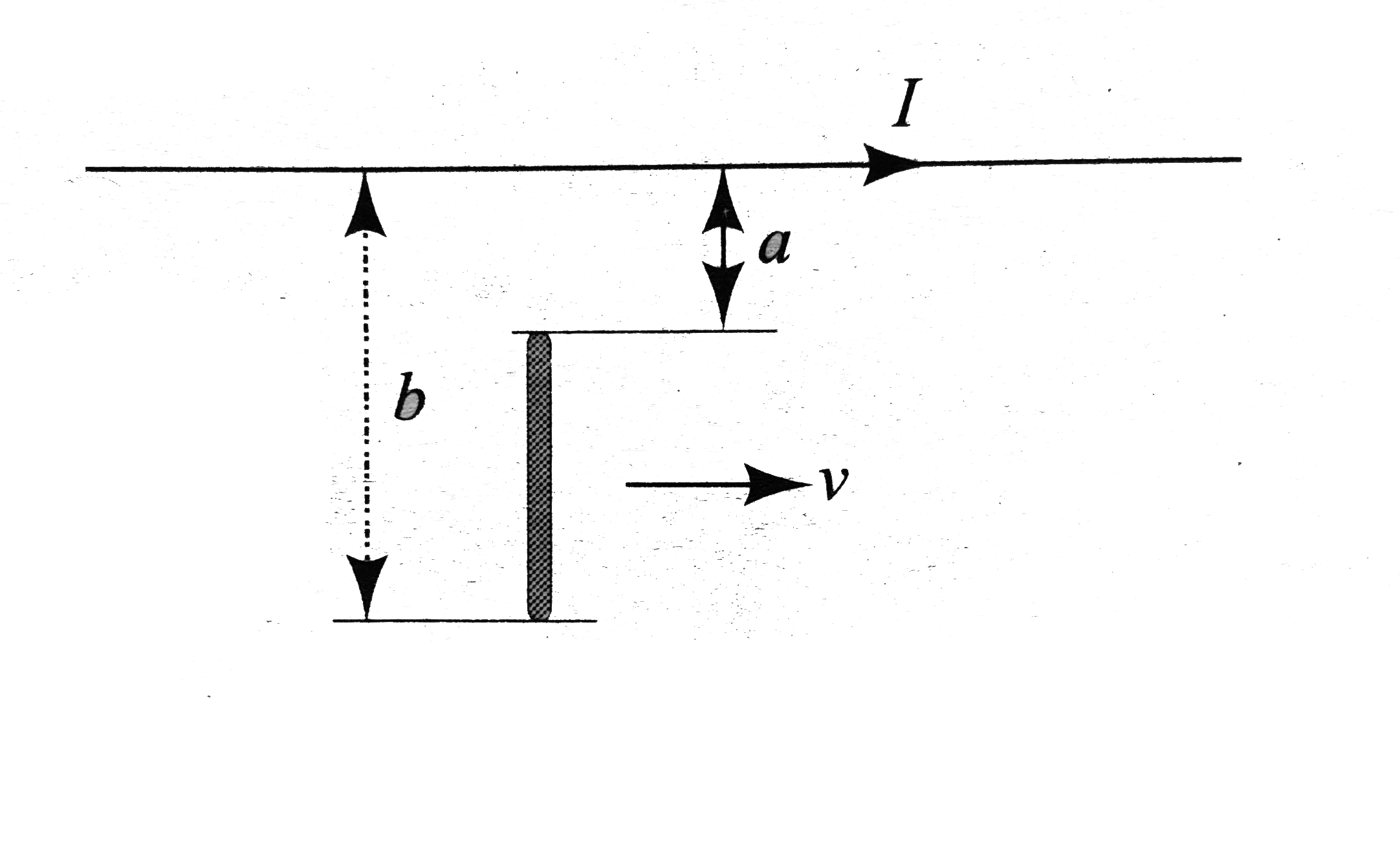
View SolutionShows a copper rod moving with velocity v parallel to a long straight wire carrying current =100A. Calculate the induced emf in the rod, where v=5mS−1, a=1cm , b=100cm.

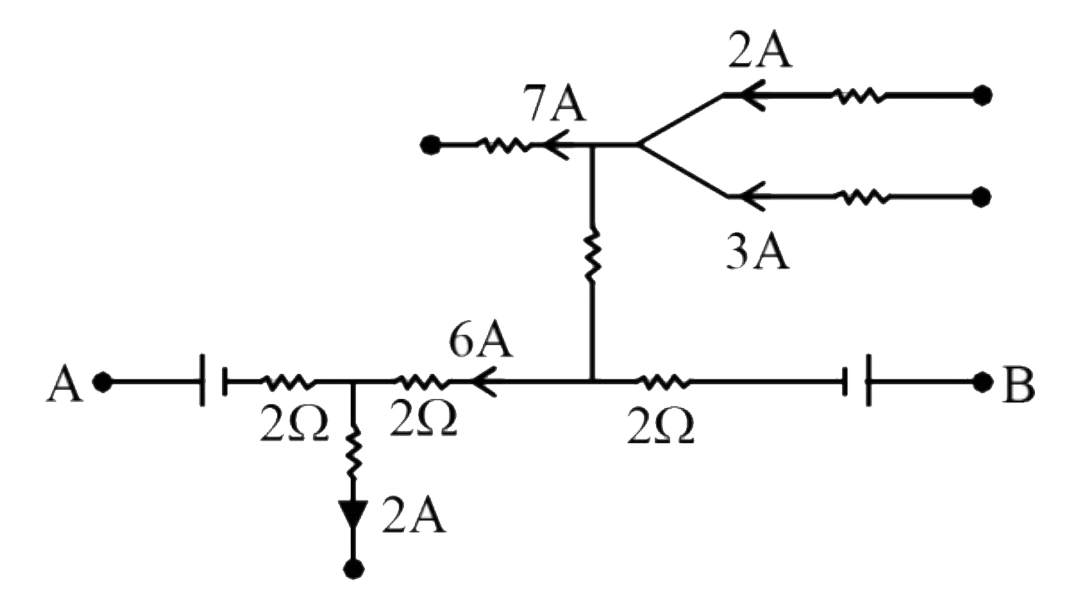
View SolutionThe potential difference (VA−VB) between the point A and B in the given figure is

View SolutionThe potential difference (VA−VB) between the point A and B in the given figure is

View SolutionConsider a conductor of length 40 cm where a potential difference of 10V is maintained between the ends of the conductor. Find the mobility of the electrons provided the drift velocity of the electrons is 5×10⁻⁶ms−1
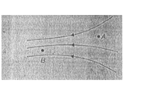
View SolutionIn figure two points A and B are located in a region of electric field . The potential difference VB−VA is

View SolutionThe figure shows a copper rod moving with velocity v parallel to a long straight wire carrying a current I = 100 A. Calculate the induced emf in the rod, assuming that v = 5 m/s, a = 1 cm and b = 100 cm.
View SolutionA coaxial cable consists of a thin inner conductor fixed along the axis of a hollow outer conductor. The two conductor carry equal currents in opposite directions. Let B1andB2 be the magnetic fields in the region between the conductors and outside the conductor, respectively. Then,
View Solution
In the above circuit diagram emf of two batteries are equal , then the potential difference VA–VB between terminals A and B will be
View Solution
