Two cities are apart . The electric power is sent from one City to another city through copper wires . The fall of potential per km is and average resistance per km is . The power loss in wire is
To solve the problem of power loss in the copper wires connecting two cities that are 80 km apart, we will follow these steps:
Step 1: Calculate the total potential difference (V) between the two cities.
Given that the fall of potential per km is 8 V, we can calculate the total potential difference over the distance of 80 km.
V=fall per km×distance=8V/km×80km=640V
Step 2: Calculate the total resistance (R) of the wire.
The average resistance per km is given as 0.25 ohms. Therefore, we can calculate the total resistance over the distance of 80 km.
R=resistance per km×distance=0.25Ω/km×80km=20Ω
Step 3: Calculate the power loss (P) using the formula P=V2R.
Now that we have both the potential difference and the resistance, we can find the power loss in the wire.
P=V2R=640220
Calculating 6402:
6402=409600
Now substituting back into the power formula:
P=40960020=20480W
Step 4: Convert power loss to kilowatts.
To express the power loss in kilowatts:
P=204801000=20.48kW
Final Answer:
The power loss in the wire is 20.48 kW.
---
Given that the fall of potential per km is 8 V, we can calculate the total potential difference over the distance of 80 km.
The average resistance per km is given as 0.25 ohms. Therefore, we can calculate the total resistance over the distance of 80 km.
Now that we have both the potential difference and the resistance, we can find the power loss in the wire.
To express the power loss in kilowatts:
The power loss in the wire is 20.48 kW.
Similar Questions
Two cities are 80 km apart. The electric power is sent from one city to another city through copper wires. The fall in potential per km is 8 V and average resistance per km is (0.25Ω). The power loss in wire is
View SolutionTwo cities are 150km apart. Electric power is sent from one city to another city through copper wire. The fall of potential per km is 8V and the average resistance per km is 0.5Ω. The power loss in the wire is
View Solution
Knowledge Check
A small town with a demand of 800 kW of electric power at 220 V is situated 15 km away from an electric plant generating power at 440 V. The resistance of the two line wires carrying power is 0.5Ω per km. The town gets power from the lines through a 4000-220 V step down transformer at a substation in the town.
Estimate the line power loss in the form of heat.
(b) How much power must the plant supply. assuming there is negligible power loss due to leakage?
(c) Characterize the step up transformer at the plant.A400 kWB600 kWC300 kWD800 W
A small town with a demand of 800 kW of electric power at 220 V is situated 15 km away from an electric plant generating power at 440 V. The resistance of the two line wires carrying power is 0.5Ω per km. The town gets power from the lines through a 4000-220 V step down transformer at a substation in the town.
(a) Estimate the line power loss in the form of heat.
(b) How much power must the plant supply. assuming there is negligible power loss due to leakage?
(c) Characterize the step up transformer at the plant.
View Solution(a) Draw the diagram of a device which is used to decrease high S voltage into a AC voltage and state its working principle. Write four sources of energy loss in this device.
(b) A small town with a demand of 1200 kW of electric power at 220 V is situated 20 Km away from an electric plant generating power at 440V. The resistance of the two wire line carrying power is 0.5Ω per km. The town gets the power from the line through a 4000-220 V step-down transformer at s sub-station in the town. Estimate the line power loss in the from of heat.
View Solution
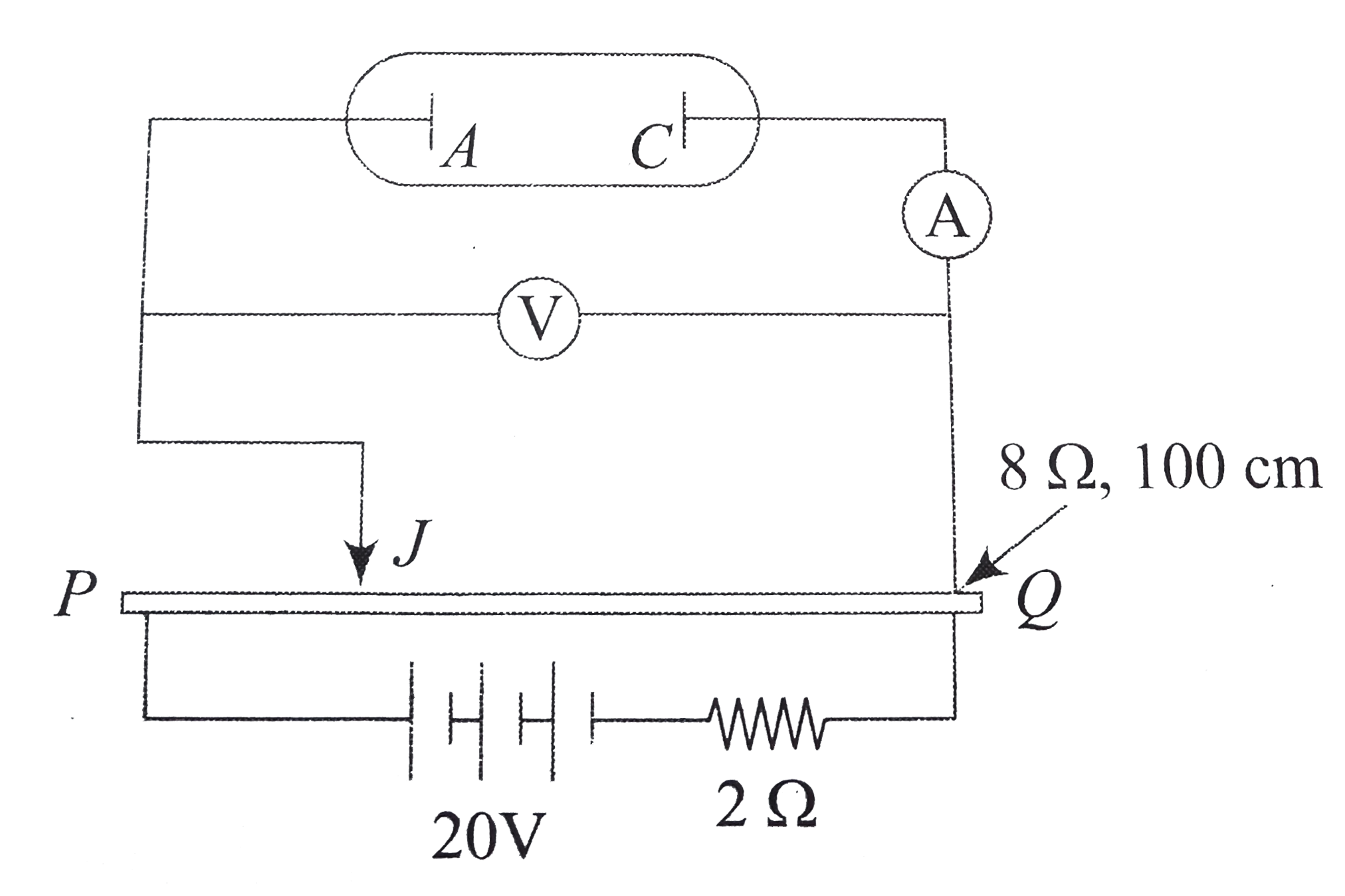
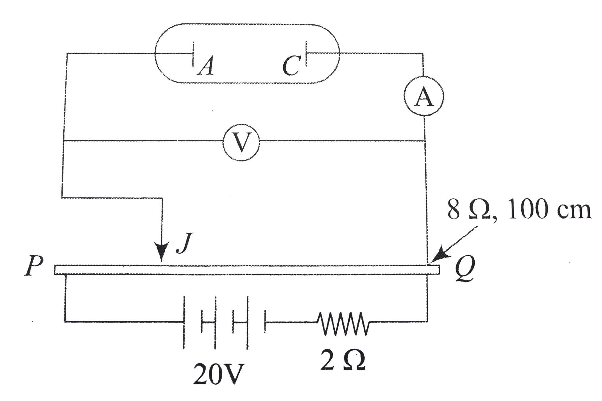
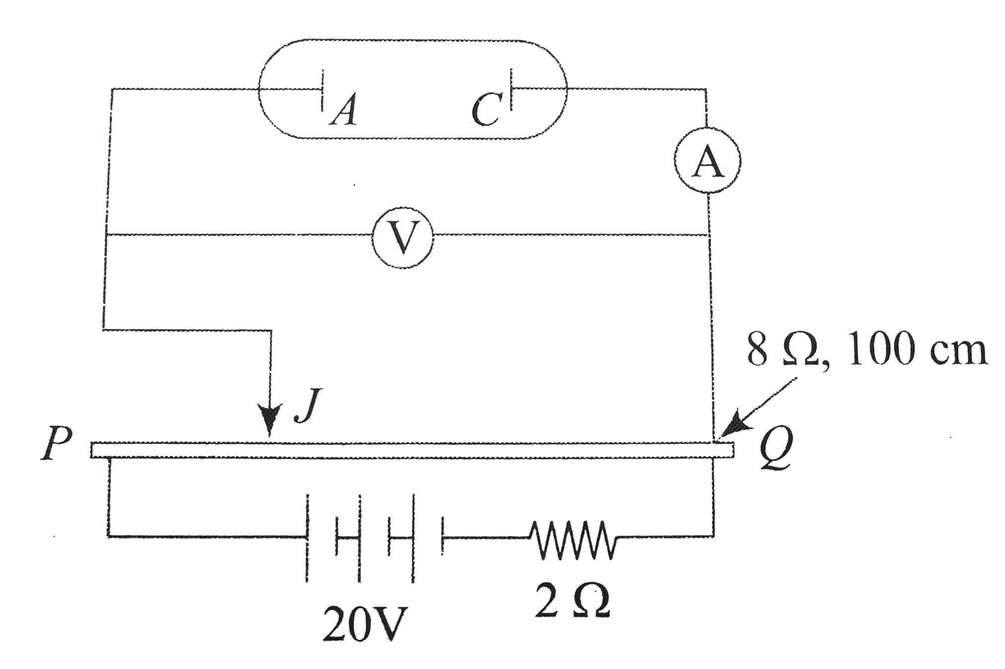
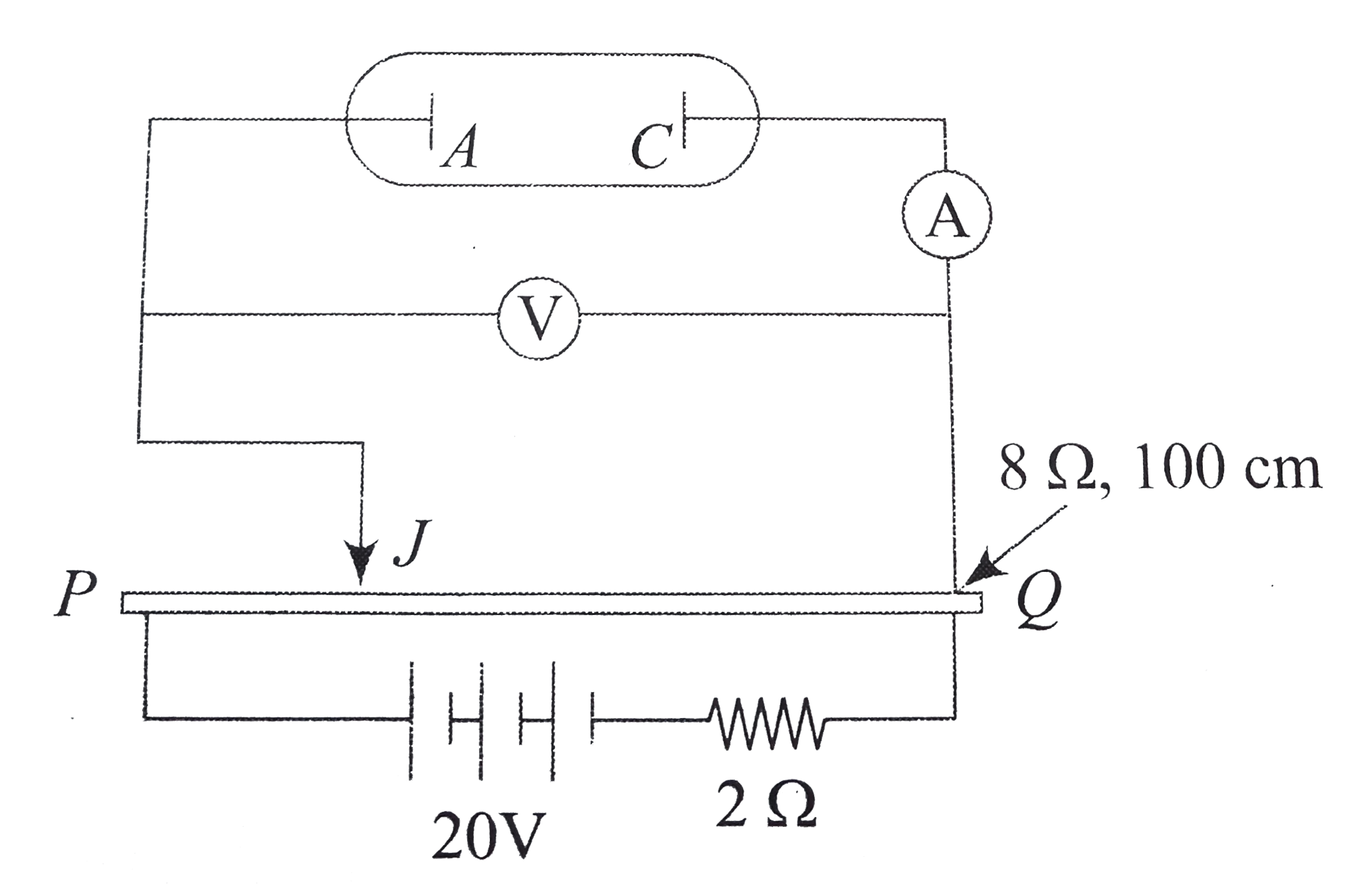
An experimental setup of verification of photoelectric effect is shown if Fig. The voltage across the electrodes is measured with the help of an ideal voltmeter, and which can be varied by moving jockey J on the potentiometer with wire. The battery used in potentiometer circuit is of 20 V and its internal resistance is 2Ω. The resistance of 100 cm long potentiometer wire is 8Ω.
The photocurrent is measured with the help of an ideal ammeter. Two plates of potassium oxide of area 50cm2 at separation 0.5mm are used in the vacuum tube. Photocurrent in the circuit is very small, so we can treat the potentiometer circuit as an independent circuit. The wavelength of various colors is as follows:
Q. It is found that ammeter current remains unchanged (2μA) even when the jockey is moved from the end P to the middle point of the potentiometer wire. Assuming that all the incident photons eject electrons and the power of the light incident is 4×10⁻⁶ W. Then, the color of the incident light is
View Solution
An experimental setup of verification of photoelectric effect is shown if Fig. The voltage across the electrodes is measured with the help of an ideal voltmeter, and which can be varied by moving jockey J on the potentiometer with wire. The battery used in potentiometer circuit is of 20 V and its internal resistance is 2Ω. The resistance of 100 cm long potentiometer wire is 8Ω.
The photocurrent is measured with the help of an ideal ammeter. Two plates of potassium oxide of area 50cm2 at separation 0.5mm are used in the vacuum tube. Photocurrent in the circuit is very small, so we can treat the potentiometer circuit as an independent circuit. The wavelength of various colors is as follows:
Q. When other light falls on the anode plate, the ammeter reading remains zero till jockey is moved from the end P to the middle point of the wire PQ. Thereafter, the deflection is recorded in the ammeter. The maximum kinetic energy of the emitted electron is
View Solution
An experimental setup of verification of photoelectric effect is shown if Fig. The voltage across the electrodes is measured with the help of an ideal voltmeter, and which can be varied by moving jockey J on the potentiometer with wire. The battery used in potentiometer circuit is of 20 V and its internal resistance is 2Ω. The resistance of 100 cm long potentiometer wire is 8Ω.
The photocurrent is measured with the help of an ideal ammeter. Two plates of potassium oxide of area 50cm2 at separation 0.5mm are used in the vacuum tube. Photocurrent in the circuit is very small, so we can treat the potentiometer circuit as an independent circuit. The wavelength of various colors is as follows:
Q. Calculate the number of electrons that appear on the surface of the cathode plate, when the jockey is connected at the end P of the potentiometer wire. Assume that no radiation is falling on the plates.
View Solution
An experimental setup of verification of photoelectric effect is shown if Fig. The voltage across the electrodes is measured with the help of an ideal voltmeter, and which can be varied by moving jockey J on the potentiometer with wire. The battery used in potentiometer circuit is of 20 V and its internal resistance is 2Ω. The resistance of 100 cm long potentiometer wire is 8Ω.
The photocurrent is measured with the help of an ideal ammeter. Two plates of potassium oxide of area 50cm2 at separation 0.5mm are used in the vacuum tube. Photocurrent in the circuit is very small, so we can treat the potentiometer circuit as an independent circuit. The wavelength of various colors is as follows:
Q. Which of the following colors may not give photoelectric effect for this cathode? if power of incident light is 4*10^-6 and currenr 2micro ampere.
View Solution
An experimental setup of verification of photoelectric effect is shown if Fig. The voltage across the electrodes is measured with the help of an ideal voltmeter, and which can be varied by moving jockey J on the potentiometer with wire. The battery used in potentiometer circuit is of 20 V and its internal resistance is 2Ω. The resistance of 100 cm long potentiometer wire is 8Ω.
The photocurrent is measured with the help of an ideal ammeter. Two plates of potassium oxide of area 50cm2 at separation 0.5mm are used in the vacuum tube. Photocurrent in the circuit is very small, so we can treat the potentiometer circuit as an independent circuit. The wavelength of various colors is as follows:
Q. When radiation falls on the cathode plate, a current of 2μA is recorded in the ammeter. Assuming that the vacuum tube setup sollows Ohm's law, the equivalent resistance of vacuum tube operating in this case when jockey is at end P is
View Solution
