The diagram shows a coil wound around a U shape soft iron bar AB.
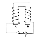
What is the polarity induced at the ends A and B when the switch is pressed ?
The polarity induced at the end A is North and at the end B is sout।
Topper's Solved these Questions
Similar Questions
The diagram shows a coil wound around a U shape soft iron bar AB.
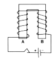
What will be the polarities at A and B if the direction of current is reversed in the circuit ?
View SolutionFig. shows a coil wound around a soft iron bar XY.
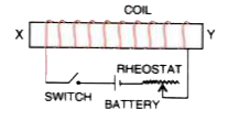
State the polarity at the ends X and Y as the switch is pressed.
View SolutionThe diagram shows a coil wound around a U shape soft iron bar AB.
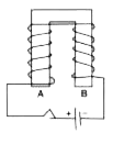
Suggest one way to strengthen the magnetic field in the electromagnet.
View SolutionFig. shows a coil wound around a soft iron bar XY.
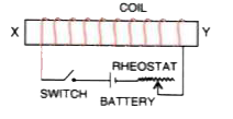
Suggest one way of increasing the strength of the electromagnet so formed.
View SolutionShows a capacitive circuit, with a switch SW.
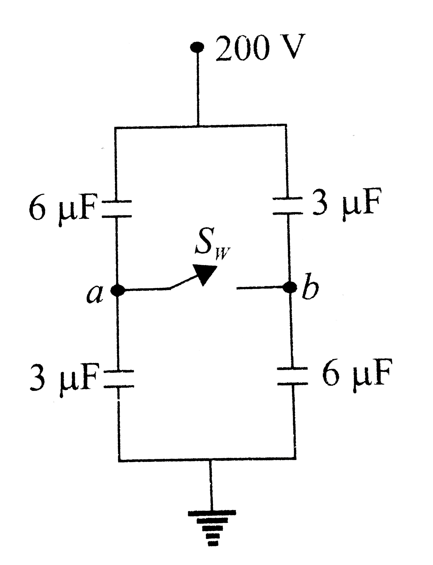 .
.
a. What is the potential difference between a and b when the switch is open?
View SolutionWhen a wire is wound around a soft iron bar, and a current is passed through it, the soft iron bar behaves like a magnet.
View SolutionDraw a labelled diagram to make an electro magnet from a soft iron bar AB. Mark the polarity at its ends. What precaution would you observe ?
View SolutionA metal rod OA of mann 'm' and length 'r' is kept rotating with a constantangular speed ω in a vertical plane about a horizontal axis at the end O. The free end A is arraged to slide without friction along fixed conduction circular ring in the same plane as that of rotation. A uniform and constant magnetic induction →B is applied perpendicular and into the plane of rotation as shown in the figure below. An inductor L and an external resistance R are connected through a swithch S between the point O and a point C on the ring to form an electrical circuit. Neglect the resistance of the ring and the rod. Initially, the switch is open.
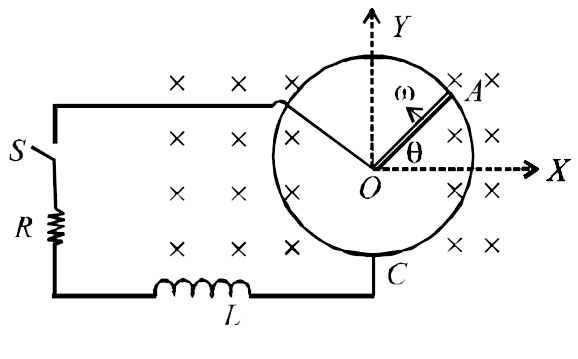
(a) What is the induced emf across the teminal of the switch?
(b) The switch S is closed at time t=0.
(i) Obtain an expression for the current as a function of time.
(ii) In the steady state, obtin the time dependence of the torque required to maintain the constant angular speed, given that the rod OA was along th positive X-axis at t=0.
View SolutionShow with the aid of a diagram how a wire is wound on a U-shaped piece of soft iron in order to make it an electromagnet. Complete the circuit diagram and label the poles of the electromagnet.
View SolutionThe diagram below shows a current carrying loop or a circular coil passing through a sheet of cardboard at the points M and N. The sheet of cardboard is sprinkled uniformly with iron filings.
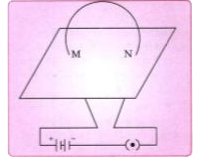
Draw the pattern of arrangement of the iron filings when current is passed through the loop.
View Solution
