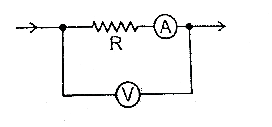
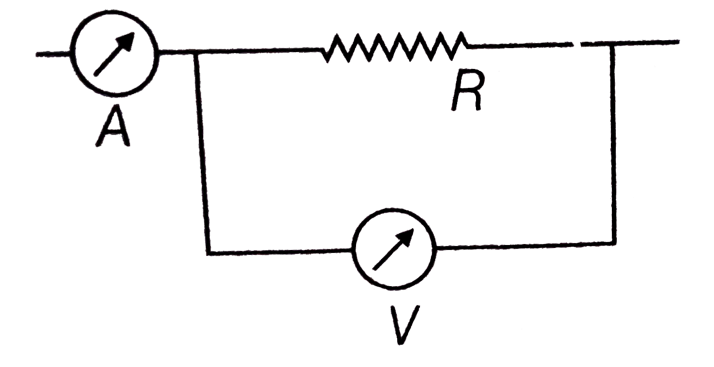
In the, Ohm's law experiment to find resistance of unknown resistor R, following two arrangement (a) and (b) are possible.

The resistance measured is given by
Rmeasured=Vi
V= voltage reading of voltmeter, i= current Reading of ammeter.
But unfortunately the ammeters and voltmeter used are not ideal, but having resistance RA and RV respectively.
For arrangement (b), the measured resistance is
R+Rv
R+RA
RRvR+Rv
RRvR+Rv+RA
Reading of Ammeter = I Reading of voltmeter =P.d across voltmeter =P.d across (R+RA) system =I(R +R_(A)<br>rArrMeasuredresistance= (V)/(i) = (i(R+R_(A))/(i) =R +R_(A)
 .
.
Topper's Solved these Questions
- BOOK - RESONANCE ENGLISHCHAPTER - EXPERIMENTAL PHYSICSEXERCISE - Exercise -2 PART -11videos
EXPERIMENTAL PHYSICS
- BOOK - RESONANCE ENGLISHCHAPTER - EXPERIMENTAL PHYSICSEXERCISE - Exercise -2 PART17videos
EXPERIMENTAL PHYSICS
- BOOK - RESONANCE ENGLISHCHAPTER - EXPERIMENTAL PHYSICSEXERCISE - PART II13videos
EXPERIMENTAL PHYSICS
- BOOK - RESONANCE ENGLISHCHAPTER - ELECTROSTATICSEXERCISE - HLP40videos
ELECTROSTATICS
- BOOK - RESONANCE ENGLISHCHAPTER - GEOMATRICAL OPTICS EXERCISE - Advance level Problems35videos
GEOMATRICAL OPTICS
Similar Questions
In the, Ohm's law experiment ot find resistance of unknown resistor R, the arrangement is as shown. The resistance measured is given by Rmeasured=ViV= voltage reading of voltmeter. i=current reading of ammeter. The ammeters and the voltmeter used are not ideal, and have resistance RA and RV respectively. For arrangement shown, the meausred resistance is
 View Solution
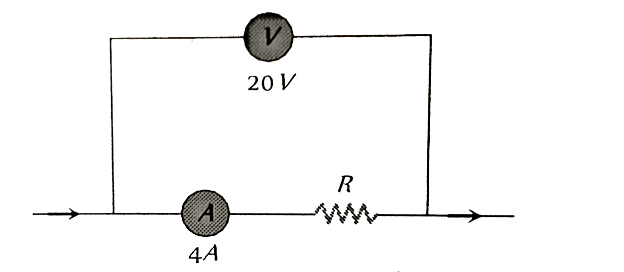
In the diagram shown, the reading of voltmeter is 20 V and that of ammeter is 4 A . The value of R should be (Consider given ammeter and voltmeter are not ideal)
 View Solution
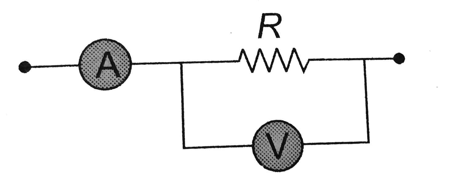
In the circuit shown the reading of ammeter and voltmeter are 4A and 20V respectively. The meters are non ideal, then R ia
 View Solution
An ammeter and a voltmeter are connected in series to an ideal battery of emf E. If the ammeter reads I and voltmeter reading V, then
View SolutionIn the circuit shown alongside, the ammeter and the voltmeter redings are 3A and 6V, respectively. Then, the value of the resistance R is
 View Solution
If the ammeter in given circuit reads 1 A, then resistance R is
View SolutionThe power dissipated in resistor R3 shown in the figure is 15 W. The reading the ammeter is 500 mA and the reading of the voltmeter is 10 V. Ammeter, voltmeter and battery are ideal.
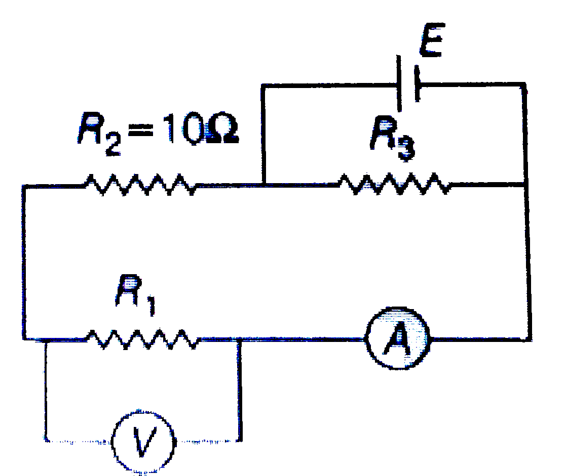
Find the resistance R1View SolutionThe power dissipated in resistor R3 shown in the figure is 15 W. The reading the ammeter is 500 mA and the reading of the voltmeter is 10 V. Ammeter, voltmeter and battery are ideal.
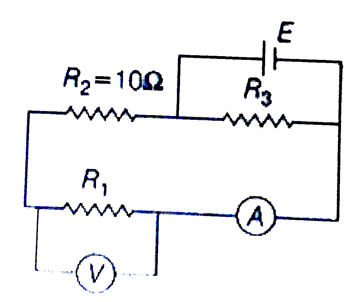
Find the resistance R3View SolutionIf the resistance R1 is increased (see figure), how will the reading of the ammeter and voltmeter change ?
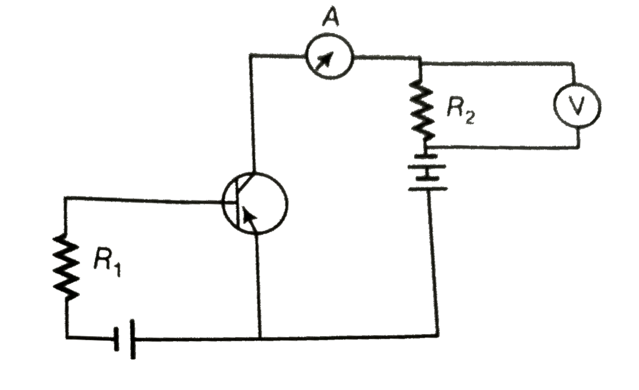 View Solution
In the adjoining circuit diagram, the readings of ammeter and voltmeter are 2 A and 120 V, respectively. If the value of R is 75Ω, then the voltmeter resistance will be
 View Solution


