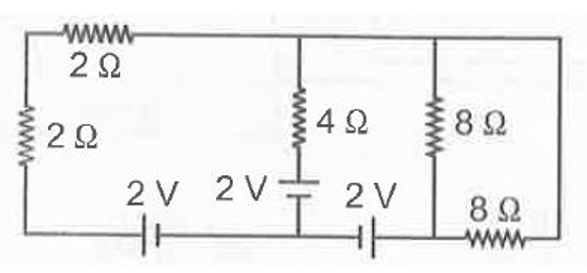
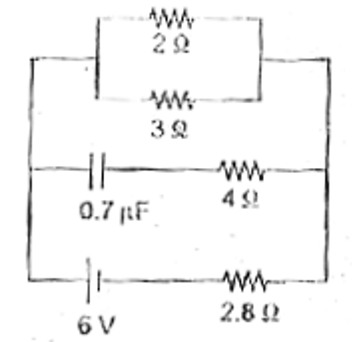
Calculate the steadystate current in the 2Ω resistor shown in the circuit in the figure. The internal resistance of the battery is negligible and the capacitance of the condenser C is 0.2μF.
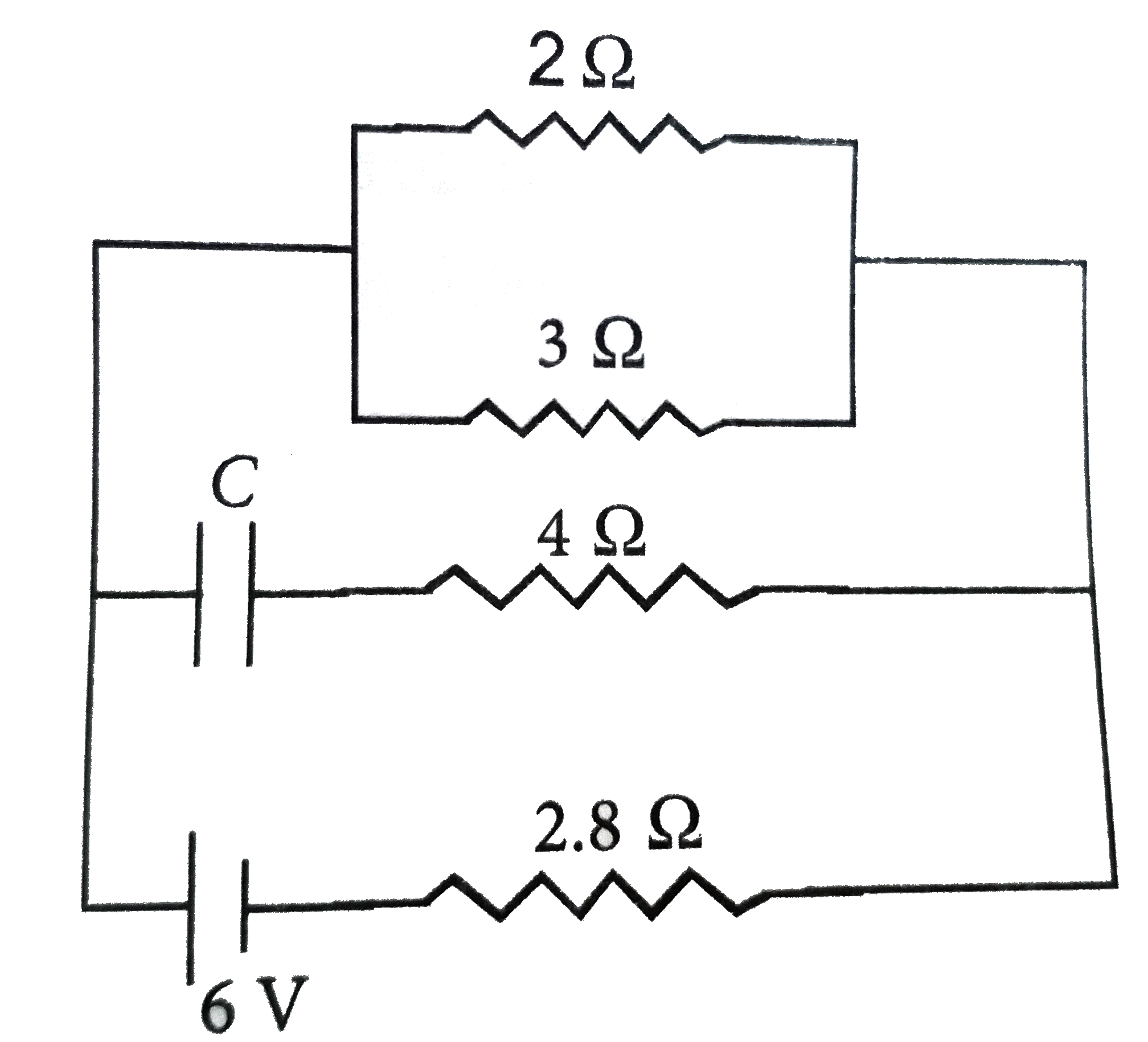
The correct Answer is:9
Step by step video & image solution for Calculate the steadystate current in the 2Omega resistor shown in the circuit in the figure. The internal resistance of the battery is negligible and the capacitance of the condenser C is 0.2 muF. by Physics experts to help you in doubts & scoring excellent marks in Class 12 exams.
Updated on:21/07/2023Topper's Solved these Questions
- CAPACITANCEBOOK - RESONANCE ENGLISHCHAPTER - CAPACITANCEEXERCISE - Exercise - 3
26 Videos
- CAPACITANCEBOOK - RESONANCE ENGLISHCHAPTER - CAPACITANCEEXERCISE - High Level Problems
16 Videos
- CAPACITANCEBOOK - RESONANCE ENGLISHCHAPTER - CAPACITANCEEXERCISE - Exercise - 1
79 Videos
- ATOMIC PHYSICSBOOK - RESONANCE ENGLISHCHAPTER - ATOMIC PHYSICSEXERCISE - Advanved level problems
17 Videos
- COMMUNICATION SYSTEMSBOOK - RESONANCE ENGLISHCHAPTER - COMMUNICATION SYSTEMSEXERCISE - Exercise 3
13 Videos
Similar Questions
Knowledge Check
Calculate the steady state current in the 2- ohm resistor shown in the circuit in the figure. The intermal resistance of the battery is negligible and the capacitance of the condenser C is 0.2 microfarad.
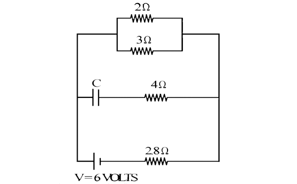 A0.6AB0.9AC1.2AD0.1A
The steady state current in a 2Ω resistor when the internal resistance of the battery is negligible and the capacitance of the condenser is 0.1μF is
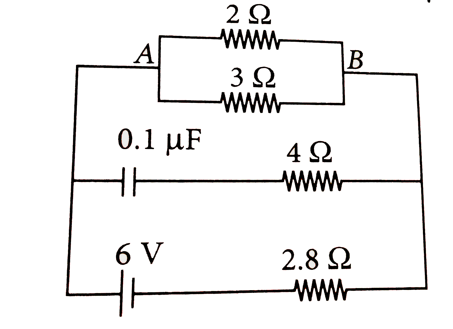 A0.6AB0.9AC1.5AD0.3A
For the circuit shown in the figure, the current in the 4Ω resistor is
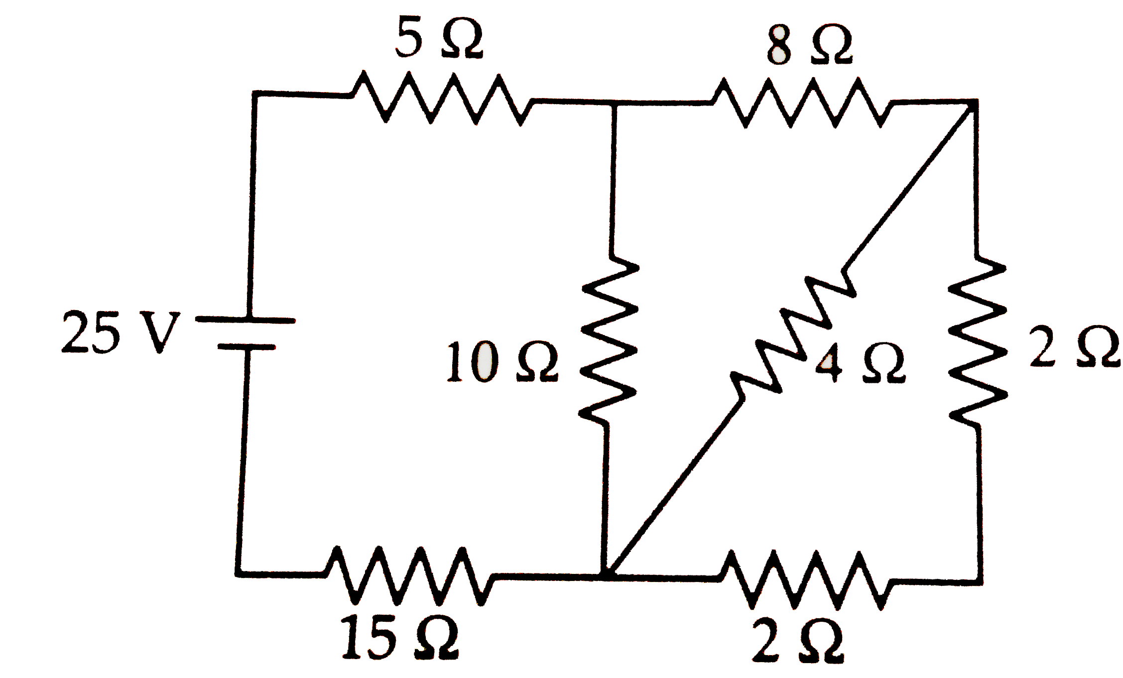 A0.5AB0.25AC1AD1.5A
Consider the circuit shown in fig 5.168. Find out the steady - state current in the 4Ω resistor. Assume the internal resistance of 8 V battery to be negligible.
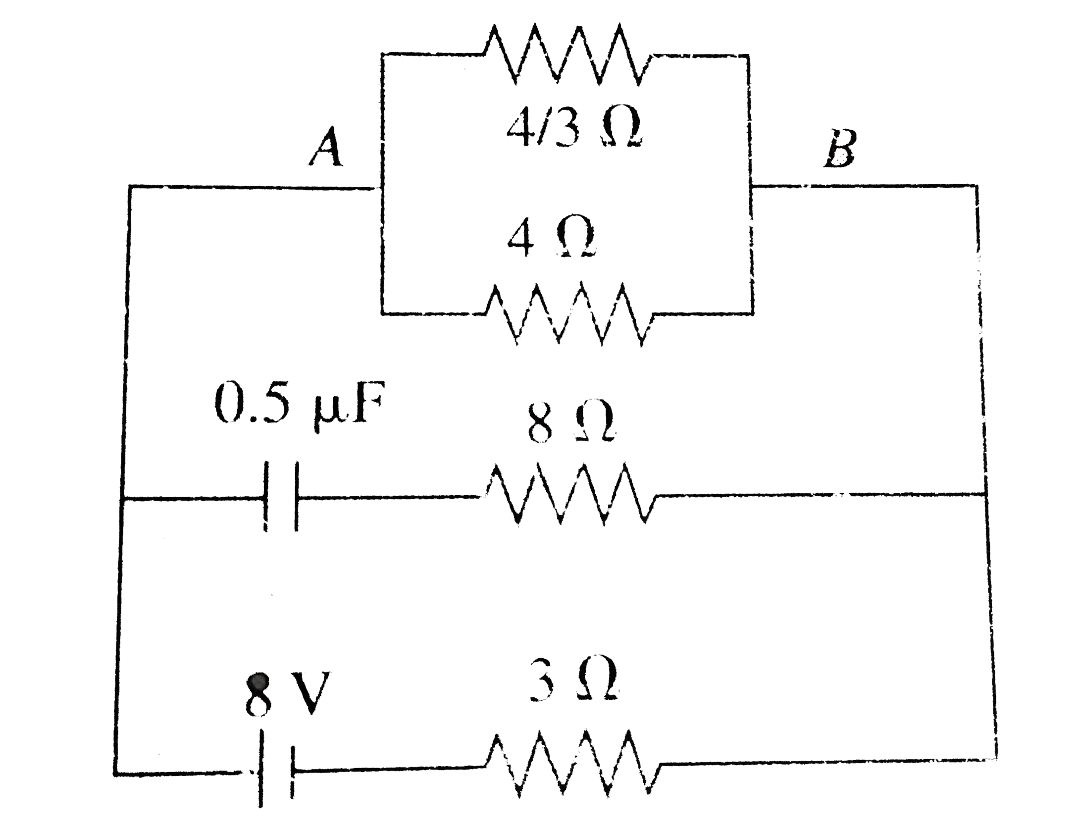
View SolutionA capacitor of 4μF is connected as shwon in the figure. The internal resistance of the battery is 0.5Ω. The amount of charge on the capacitor plates will be
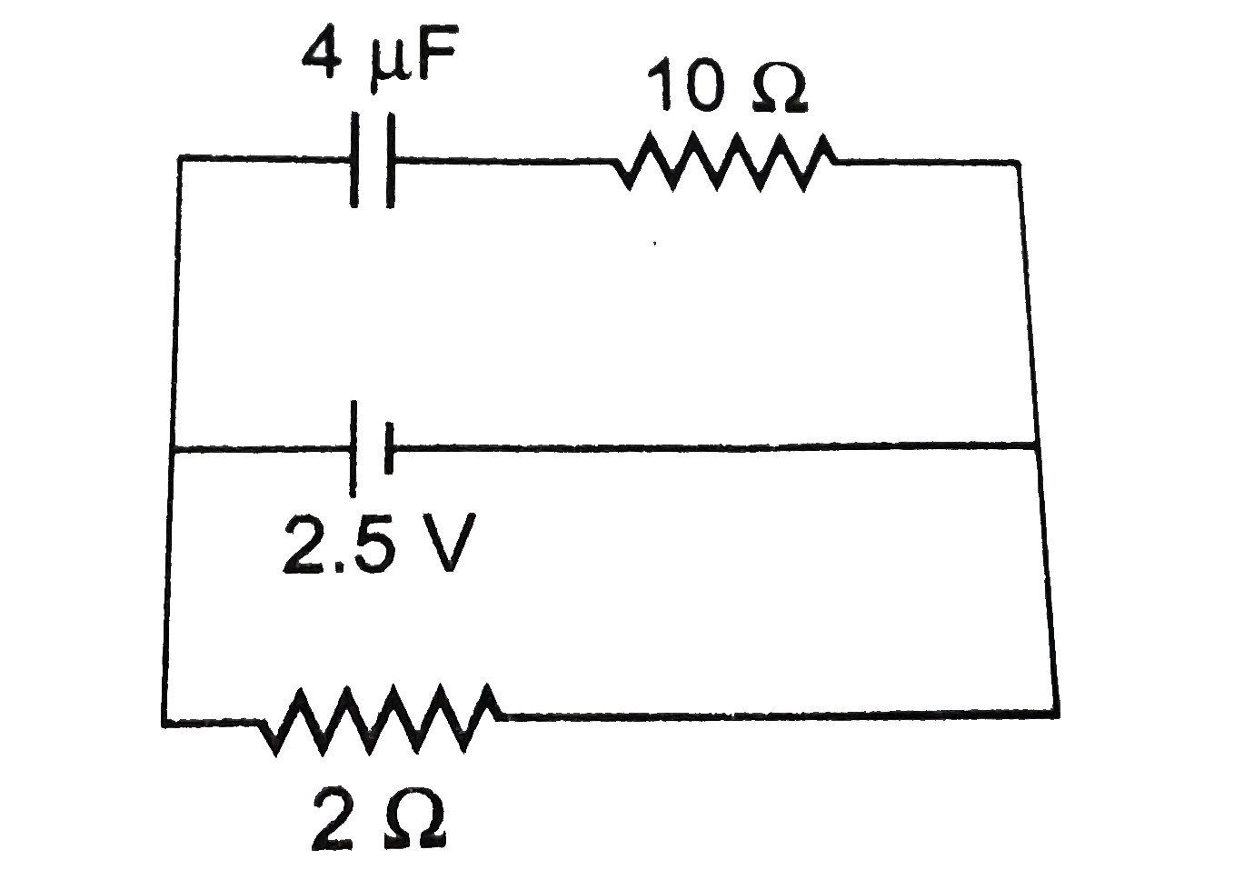
View SolutionAn inductor of inductance L = 400 mH and resistors of resistance R1=2Ω and R2=2Ω are connected to a battery of emf 12 V as shown in the figure. The internal resistance of the battery is negligible. The switch S is closed at t=0. The potential drop across L as a function of time is
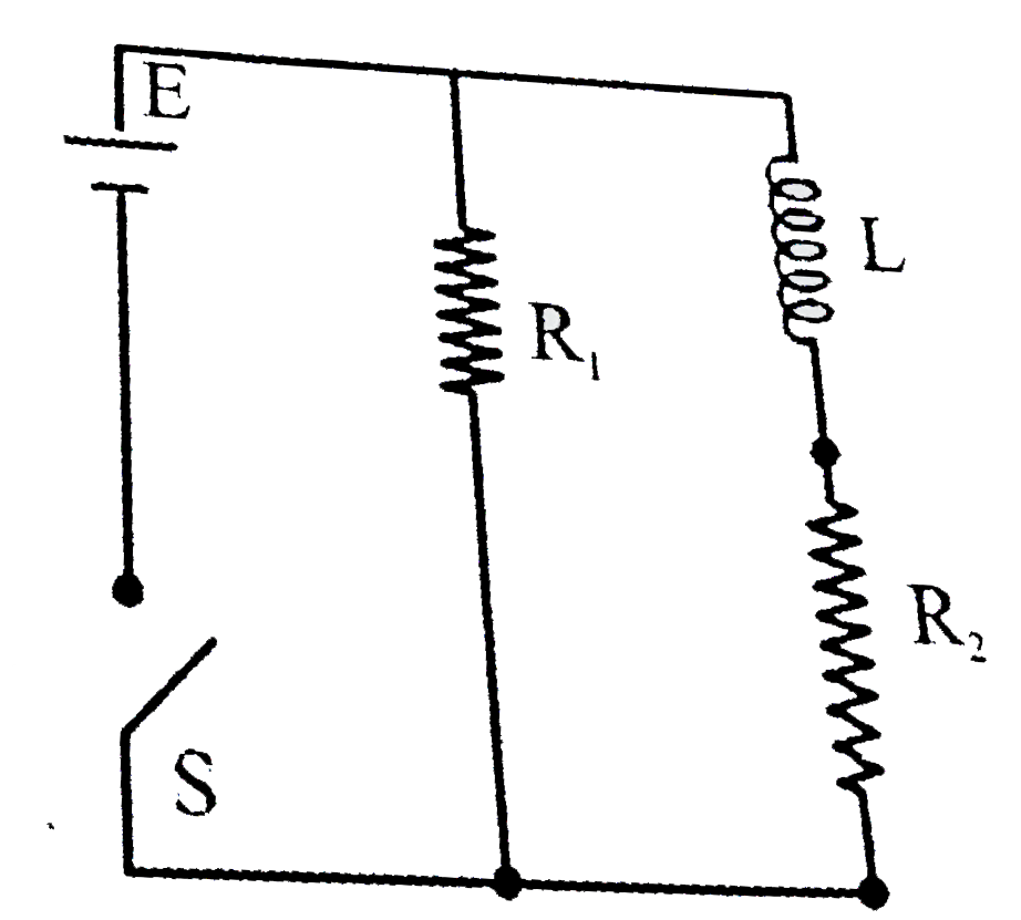
View SolutionAn inductor of inductance L = 400 mH and resistors of resistance R1=2Ω and R2=2Ω are connected to a battery of emf 12 V as shown in the figure. The internal resistance of the battery is negligible. The switch S is closed at t=0. The potential drop across L as a function of time is

View SolutionAn inductor of inductance L = 400 mH and resistors of resistance R1=2Ω and R2=2Ω are connected to a battery of emf 12 V as shown in the figure. The internal resistance of the battery is negligible. The switch S is closed at t=0. The potential drop across L as a function of time is

View Solution

