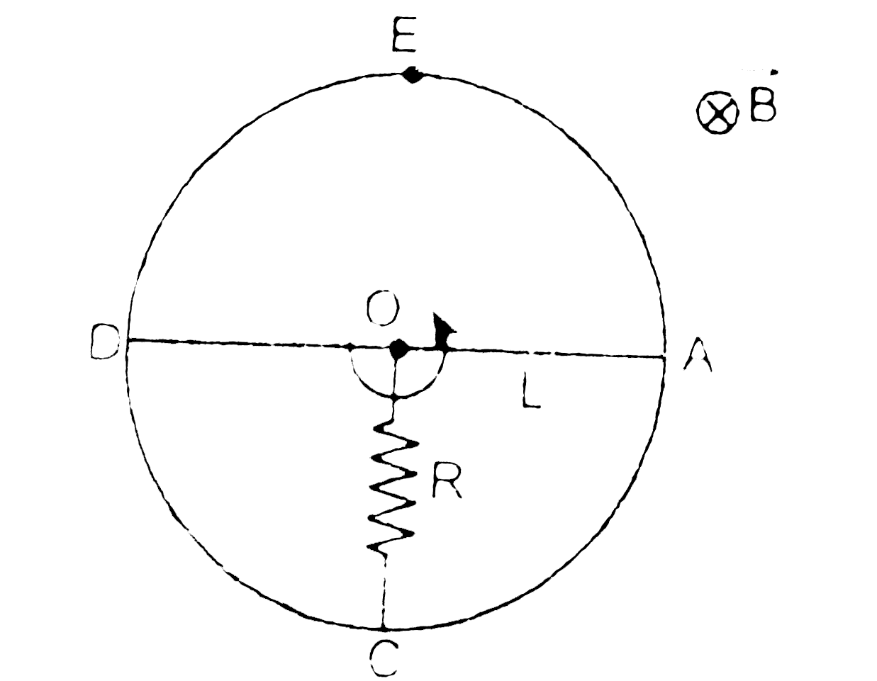
Solve problem 15 if the length of rod is 2L and resistance 2r and it is rotating about its center. Both ends of the rod now touch the conducting ring.
To solve the problem step-by-step, we need to analyze the situation involving a rod of length 2L and resistance 2R rotating about its center while touching a conducting ring.
Step 1: Understand the Setup
- We have a rod of length 2L that is rotating about its center.
- The rod has a resistance of 2R.
- The ends of the rod touch a conducting ring.
- The magnetic field is directed into the plane of rotation.
Step 2: Determine the Effective Length of the Rod
Since the rod is of length 2L, when it rotates, each half of the rod (length L) will contribute to the induced EMF.
Step 3: Calculate the Induced EMF
The induced EMF (E) in a rotating rod can be calculated using the formula:
E=12BωL2
where:
- B is the magnetic field strength,
- ω is the angular velocity,
- L is the length of one half of the rod.
Since the total length of the rod is 2L, we will use L for the calculation of the EMF.
Step 4: Analyze the Circuit
The circuit can be represented as follows:
- The rod acts as a source of EMF.
- The resistance of the rod is 2R.
- The equivalent resistance of the two halves of the rod in parallel can be calculated as:
Req=R2
Step 5: Total Resistance in the Circuit
The total resistance in the circuit will be the sum of the equivalent resistance of the rod and the resistance of the conducting ring:
Rtotal=R+Req=R+R2=3R2
Step 6: Calculate the Current
Using Ohm's law, the current (I) in the circuit can be calculated as:
I=ERtotal=12BωL23R2=BωL23R
Final Result
Thus, the current flowing through the circuit is given by:
I=BωL23R
- We have a rod of length 2L that is rotating about its center.
- The rod has a resistance of 2R.
- The ends of the rod touch a conducting ring.
- The magnetic field is directed into the plane of rotation.
Since the rod is of length 2L, when it rotates, each half of the rod (length L) will contribute to the induced EMF.
The induced EMF (E) in a rotating rod can be calculated using the formula:
E=12BωL2
where:
- B is the magnetic field strength,
- ω is the angular velocity,
- L is the length of one half of the rod.
The circuit can be represented as follows:
- The rod acts as a source of EMF.
- The resistance of the rod is 2R.
- The equivalent resistance of the two halves of the rod in parallel can be calculated as:
Req=R2
The total resistance in the circuit will be the sum of the equivalent resistance of the rod and the resistance of the conducting ring:
Rtotal=R+Req=R+R2=3R2
Using Ohm's law, the current (I) in the circuit can be calculated as:
I=ERtotal=12BωL23R2=BωL23R
Thus, the current flowing through the circuit is given by:
I=BωL23R
Similar Questions
Solve the above question if the length of rod is 2L and resistance 2r and it is rotating about its centre.Both ends of the rod now touch the conductiing ring
 View Solution
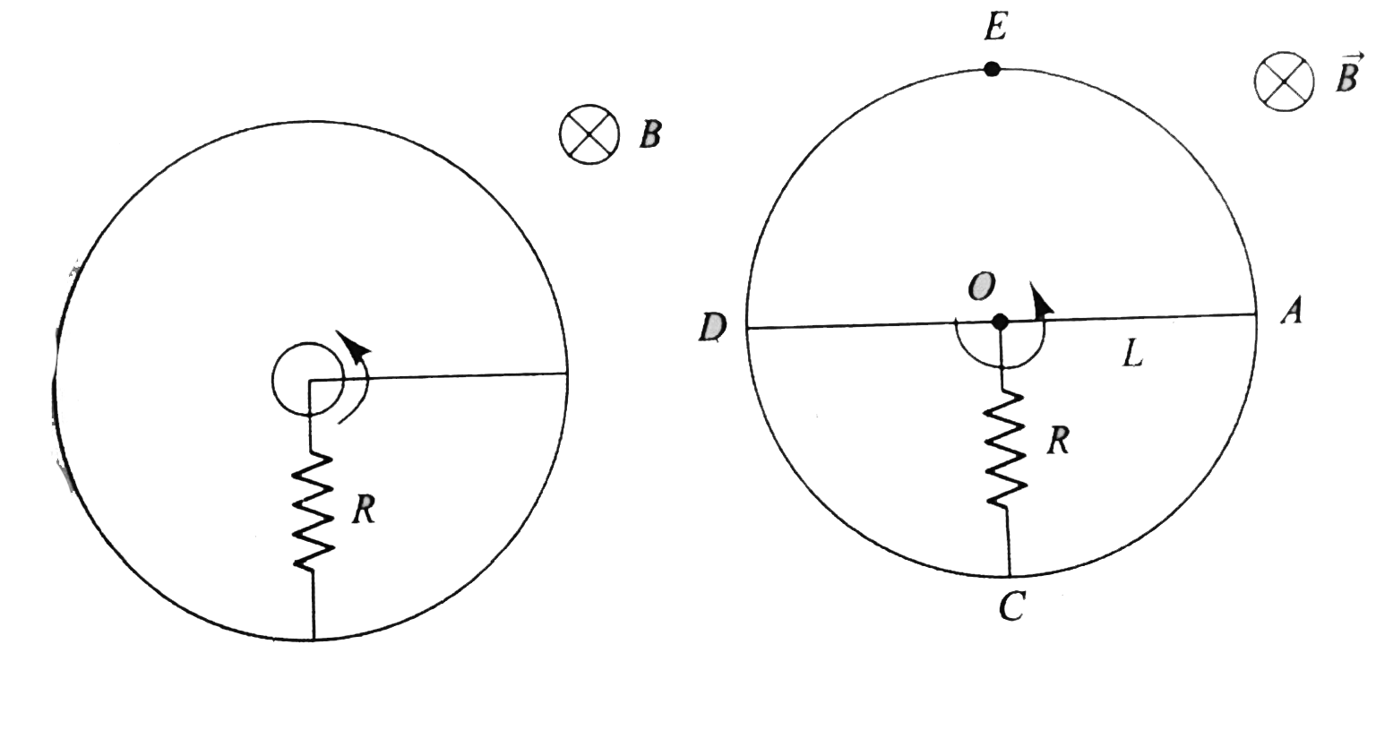
A rod of length L and resistance r rotates about one end as shown in . Its other end touches a conducting ring of negligible resistence. A resistence R is connected between the center and periphery. Draw the electrical equivalence and find the current in resistance R. There is a uniform magnetic field B directed as shown in .
 View Solution
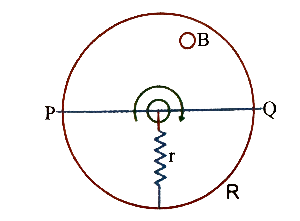
In the figure shown 'R' is a fixed conducting fixed ring of negligible resistance and radius 'a' PQ is a uniform rod of resistance r. It is hinged at the centre of the ring and rotated about this point in clockwise direction with a uniform angular velocity w. These is a uniform magnetic filled of strength 'B' ponting inwards. 'r' is a stationary resistance
 View Solution
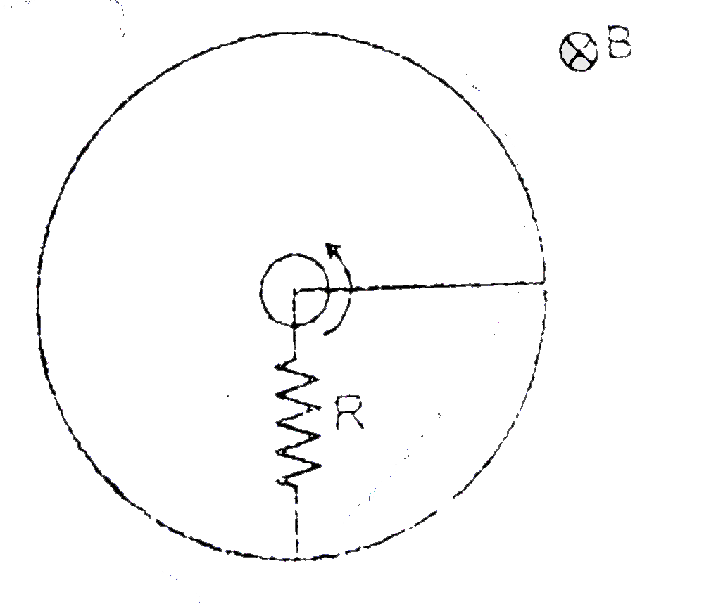
A rod of length l and resistance r rotates about one end as shown in figure.Its othr end touches a conducting ring a of negligible resistance.A resistance R is connected between centre and periphery.Draw the electrical equivalence and find the current in the resistance R.There is a uniform magnetic field B directed as shown.
 View Solution
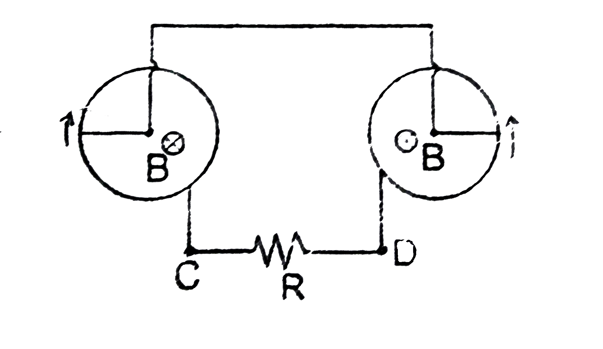
In the figure there are two identical conducting rods each of length a rotating with angular speed ω is the direction shown.One end of each rod touches a conducting ring.Magnetic field B exists perpendicular to the plane of the rings.The rods the conducting rings and the lead wires and resistanceless.Find the magnitude and direction of current in the resistance R.
 View Solution
A uniform rod of length l is from rest such that it rotates about a smooth pivot. The angular speed of the rod when it becomes vertical is.
 .View Solution
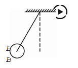
A metal rod of length 'L' and mass 'm' is pivoted at one end. A thin disk of mass 'M' and radius 'R' (< L) is attached at its centre to the free end of the rod. Consider two ways the disc is attached: (case A) - The disc is not free to rotate about its centre and (case B) - the disc is free to rotate about its centre. The rod-disc system after being released from the same displaced position. Which of the following statement(s) is(are) true?
 View Solution
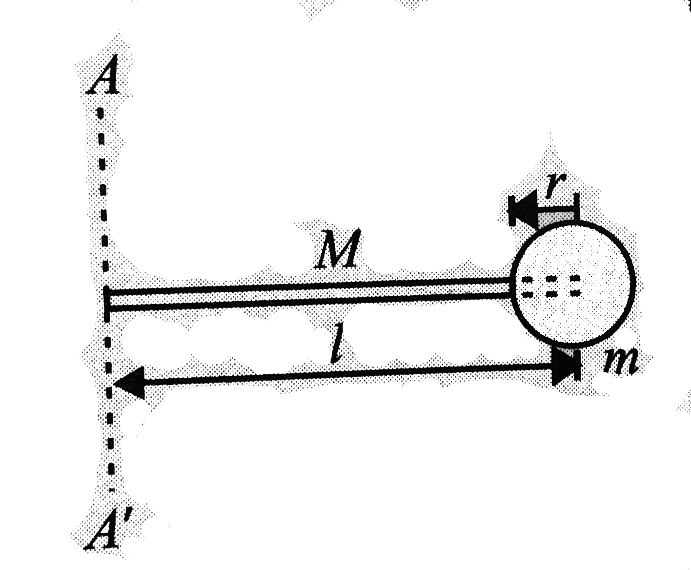
Find the moment of inertia A of a spherical ball of mass m and radius r attached at the end of a straight rod of mass M and length l, if this system is free to rotate about an axis passing through the end of the rod (end of the rod opposite to sphere).
 View Solution
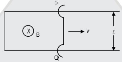
A rod having length l and resistance R is moving with velocity v on a π shape conductor. Find the current in the rod.
 View Solution

