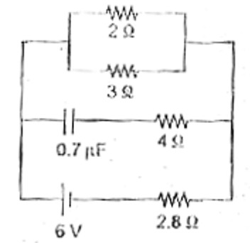
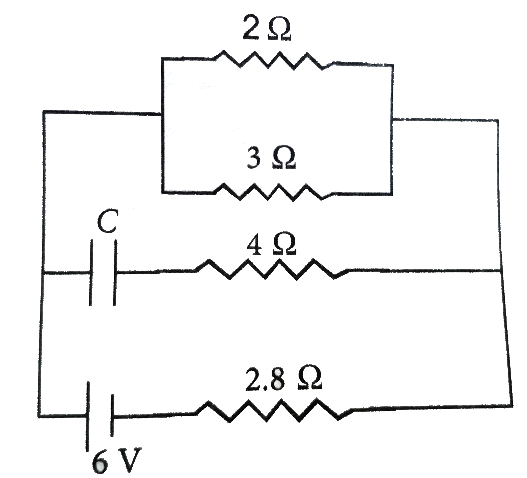
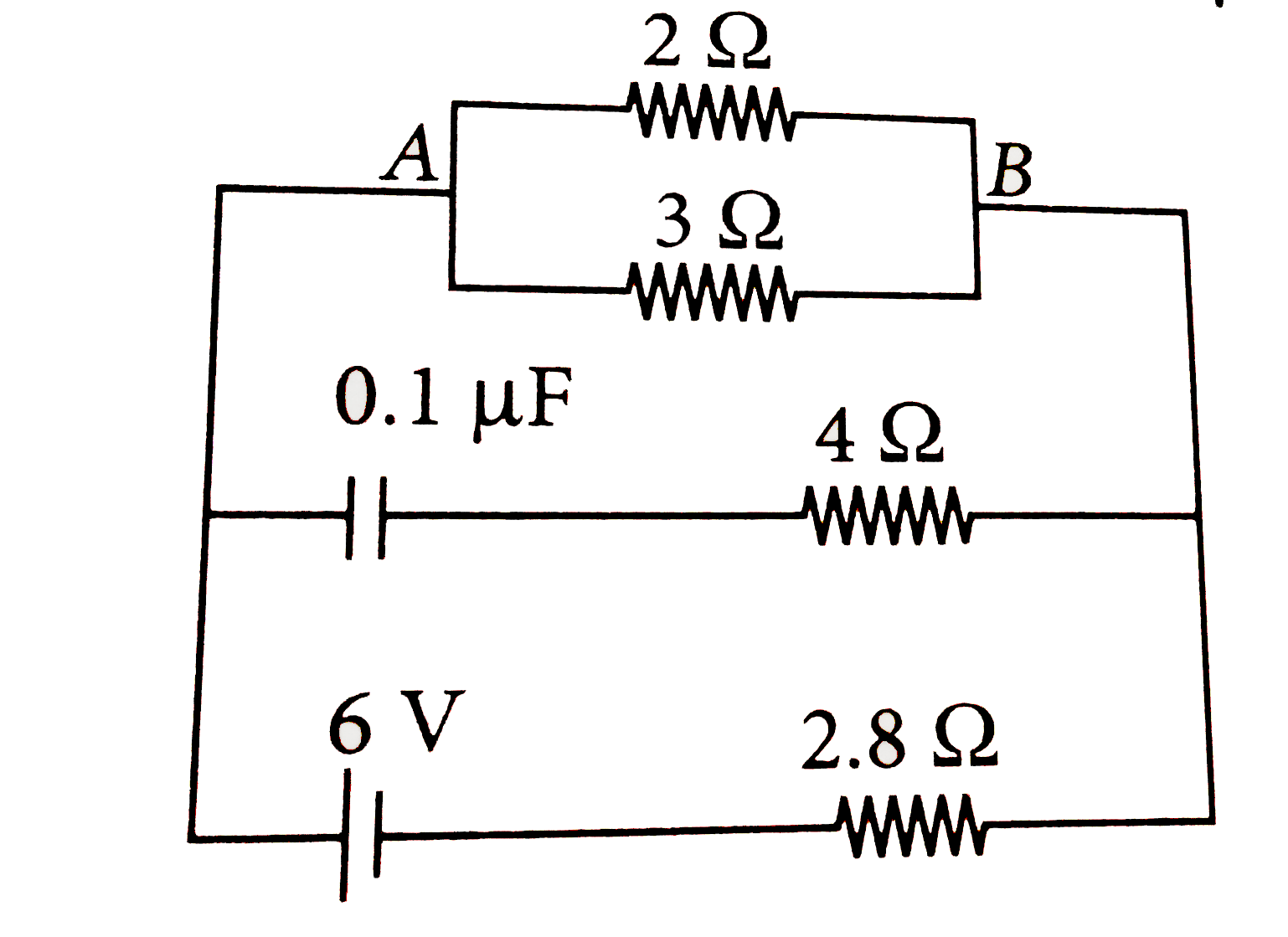
Calculate the steadystate current in the 2Ω resistor shown in the circuit in the figure. The internal resistance of the battery is negligible and the capacitance of the condenser C is 0.2μF.
The correct Answer is:0.9
In steady state situation no current will flow through the capacitor 2Ωand3Ω are in parallel.
R=2×32+3=1.2Ω, Net Current through the battry i=61.2+2.8=1.5A
The current will distribute in inverse ratio of their risistance in 2Ωand3Ω
∴i2i3=32ori2=(33+2)(1.5)=0.9A
Topper's Solved these Questions
- BOOK - VMC MODULES ENGLISHCHAPTER - CAPACITORSEXERCISE - JEE Advance ( Archive ) LEVEL 321videos
CAPACITORS
- BOOK - VMC MODULES ENGLISHCHAPTER - CAPACITORSEXERCISE - JEE Advance ( Archive ) LEVEL 331videos
CAPACITORS
- BOOK - VMC MODULES ENGLISHCHAPTER - CAPACITORSEXERCISE - JEE Advance ( Archive ) LEVEL 301videos
CAPACITORS
- BOOK - VMC MODULES ENGLISHCHAPTER - BASIC MATHEMATICS & VECTORSEXERCISE - Impeccable50videos
BASIC MATHEMATICS & VECTORS
- BOOK - VMC MODULES ENGLISHCHAPTER - CURRENT ELECTRICITYEXERCISE - IN-CHAPTER EXERCISE-F10videos
CURRENT ELECTRICITY
Similar Questions
Knowledge Check
- Question 1 - Select One
Calculate the steady state current in the 2- ohm resistor shown in the circuit in the figure. The intermal resistance of the battery is negligible and the capacitance of the condenser C is 0.2 microfarad.
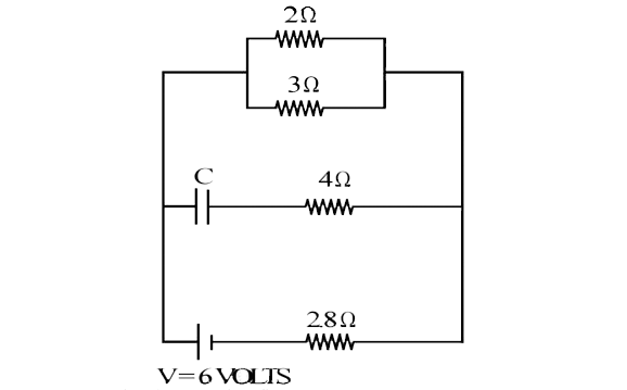 A0.6AB0.9AC1.2AD0.1A
 - Question 2 - Select One
The steady state current in a 2Ω resistor when the internal resistance of the battery is negligible and the capacitance of the condenser is 0.1μF is
 A0.6AB0.9AC1.5AD0.3A
 - Question 3 - Select One
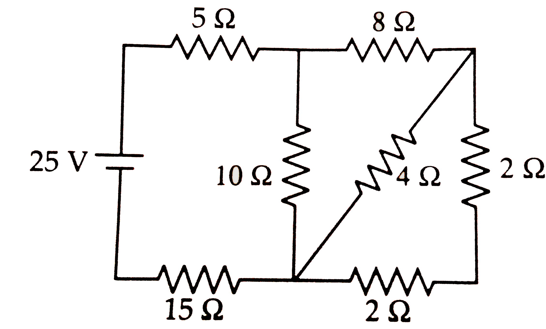
For the circuit shown in the figure, the current in the 4Ω resistor is
 A0.5AB0.25AC1AD1.5A
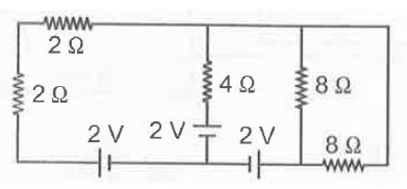
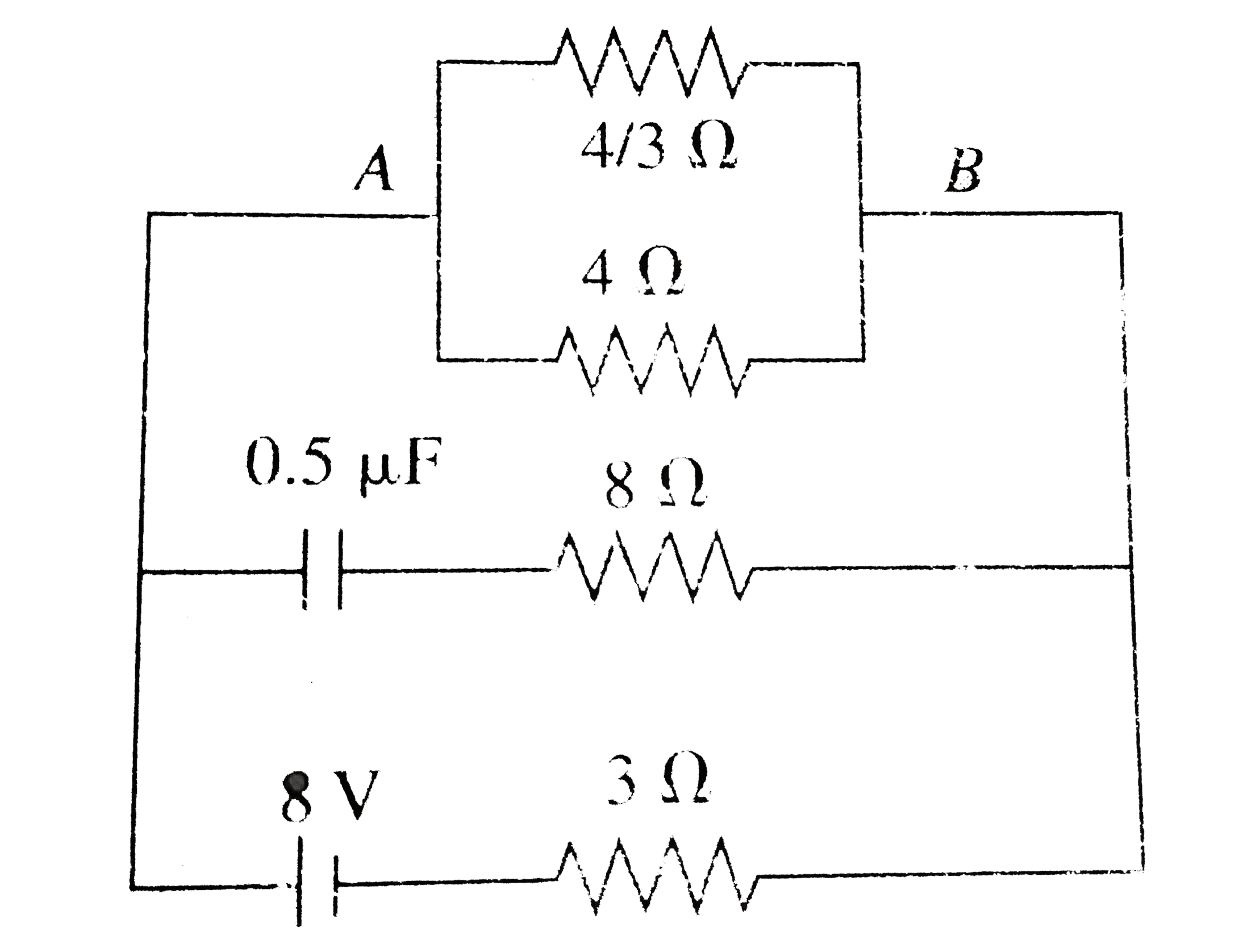
Consider the circuit shown in fig 5.168. Find out the steady - state current in the 4Ω resistor. Assume the internal resistance of 8 V battery to be negligible.
 View Solution
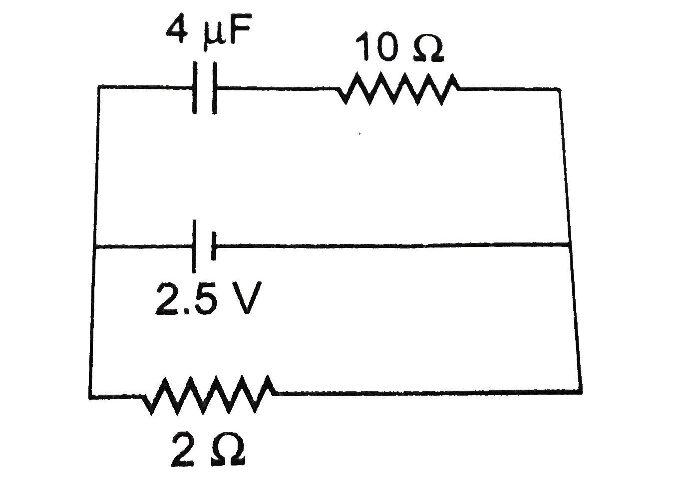
A capacitor of 4μF is connected as shwon in the figure. The internal resistance of the battery is 0.5Ω. The amount of charge on the capacitor plates will be
 View Solution
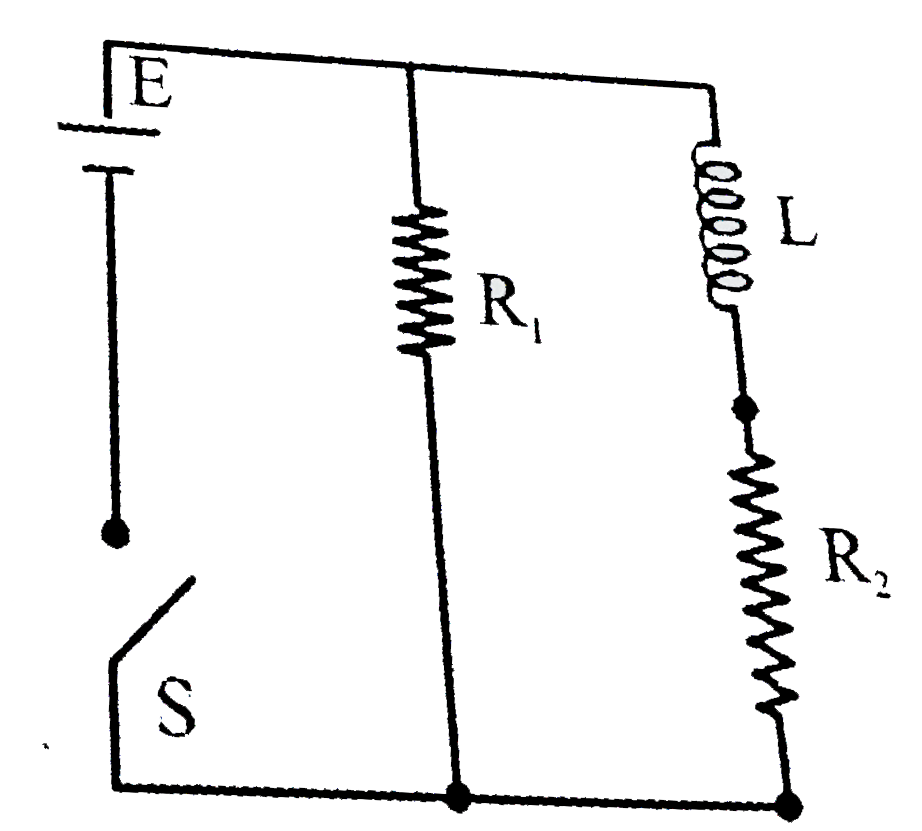
An inductor of inductance L = 400 mH and resistors of resistance R1=2Ω and R2=2Ω are connected to a battery of emf 12 V as shown in the figure. The internal resistance of the battery is negligible. The switch S is closed at t=0. The potential drop across L as a function of time is
 View Solution
An inductor of inductance L = 400 mH and resistors of resistance R1=2Ω and R2=2Ω are connected to a battery of emf 12 V as shown in the figure. The internal resistance of the battery is negligible. The switch S is closed at t=0. The potential drop across L as a function of time is
 View Solution
An inductor of inductance L = 400 mH and resistors of resistance R1=2Ω and R2=2Ω are connected to a battery of emf 12 V as shown in the figure. The internal resistance of the battery is negligible. The switch S is closed at t=0. The potential drop across L as a function of time is
 View Solution


