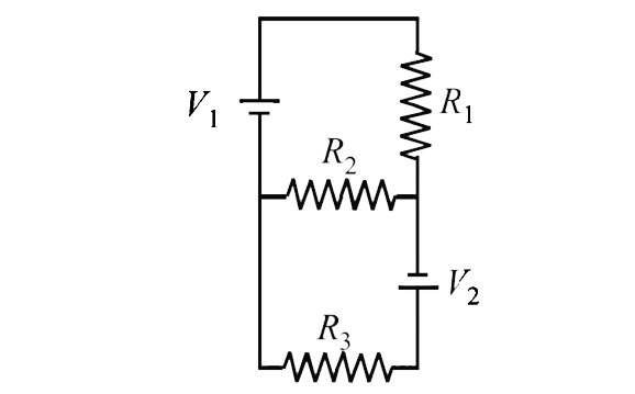
Two ideal batteries of emf V1andV2 and three resistances R1,R2andR3 are connected as shown in the figure. The current in resistance R2 would be zero if
V1=V2andR1=R2=R3
V1=V2andR1=2R2=R3
V1=2V2and2R1=2R2=R3
2V1=V2and2R1=R2=R3
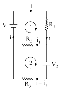
From loop 1 R2+V1=0
⇒iR1+i1R2=V1……(i)
From loop 2
i1R2−(i−i1)R3=−V2
i1(R2+R3)−iR3=V2………(ii)
Solving equation (i) and (ii)
i1(R2+R3)−iR3=−V2×R1
i1R2+iR1=V1×R3
i1(R1R2+R1R3+R2R3
We get i1=V1R3−V2R1R1+R2+R1R3+R2R3,
If i1 is zero
V1R3=V2R1
It is possible in followin options
(a) V1=V2⇒R1=R3 (b) V1=V2⇒R1=R3
Topper's Solved these Questions
- BOOK - VMC MODULES ENGLISHCHAPTER - DC CIRCUITEXERCISE - LEVEL-1 JEE MAIN ARCHIVE93videos
DC CIRCUIT
- BOOK - VMC MODULES ENGLISHCHAPTER - CURRENT ELECTRICITYEXERCISE - IN-CHAPTER EXERCISE-F10videos
CURRENT ELECTRICITY
- BOOK - VMC MODULES ENGLISHCHAPTER - DYNAMICS OF A PARTICLEEXERCISE - JEE Advance (Archive) Level - II (SINGLE OPTION CORRECT TYPE )31videos
DYNAMICS OF A PARTICLE
Similar Questions
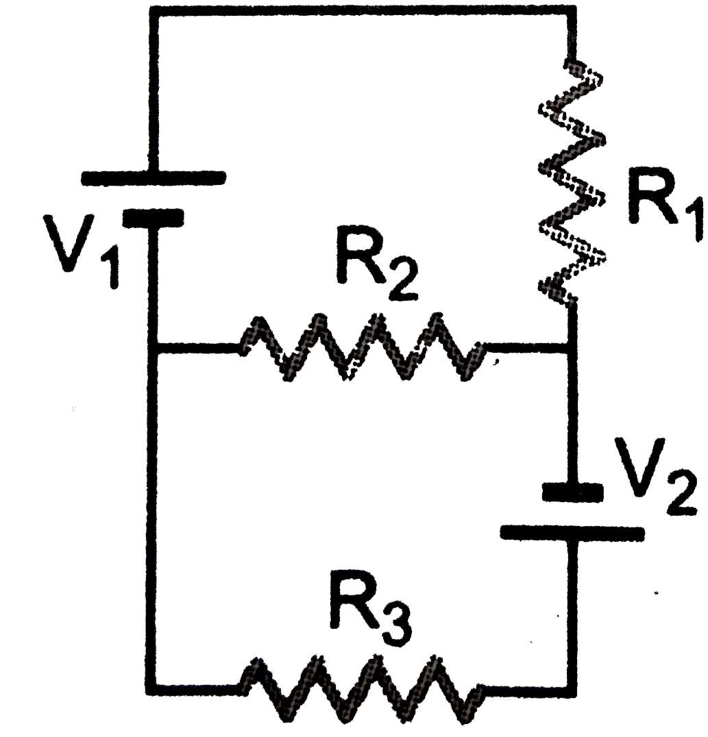
Two ideal batteries of emfV1andV2 and three resistance R1R2andR3 are connected The current in resistance R2 would be zero if
 View Solution
The given circuit has two ideal diodes connected as shown in the figure below. The current flowing through the resistance R1 will be
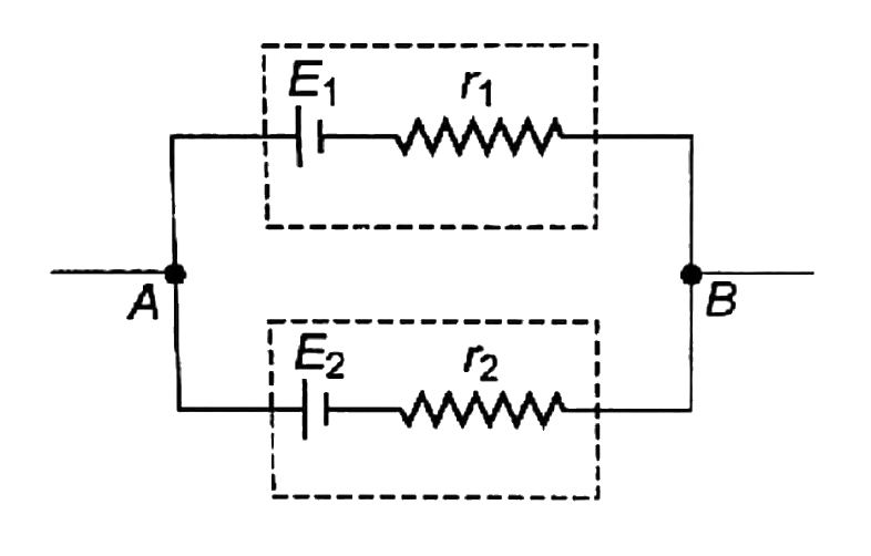
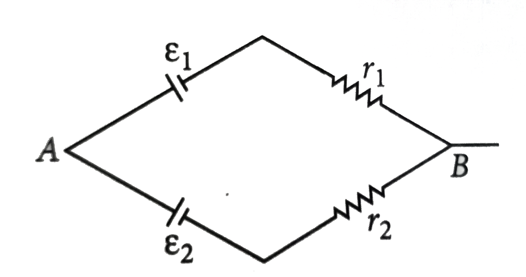
View SolutionTwo batteries of emf E1 and E2(E2>E1) and internal resistance r1 and r2 respectively are connected in parallel as shown in the figure. Then, which of the followings statements is correct ?
 View Solution
Two non-ideal batteries have e.m.f 2V and 8V respective ly and internal resistance 1 Omega and 2 Omega respectively as shown in the figure. If the potential difference between a and b is zero then the resistance R has a value
_PHY_E01_014_Q01.png) View Solution
View SolutionTwo batteries of emf E1andE2(E2>E1) and internal resistances r1andr2 respectively are connected in parallel as shown in figure.
 View Solution
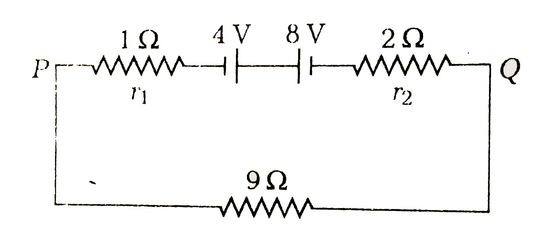
Two batteries of emf 4 V and 8 V with internal resistances 1Ω and 2Ω are connected in a circuit with a resistance of 9Ω as shown in figure. The current and potential difference between the points P and Q are
 View Solution
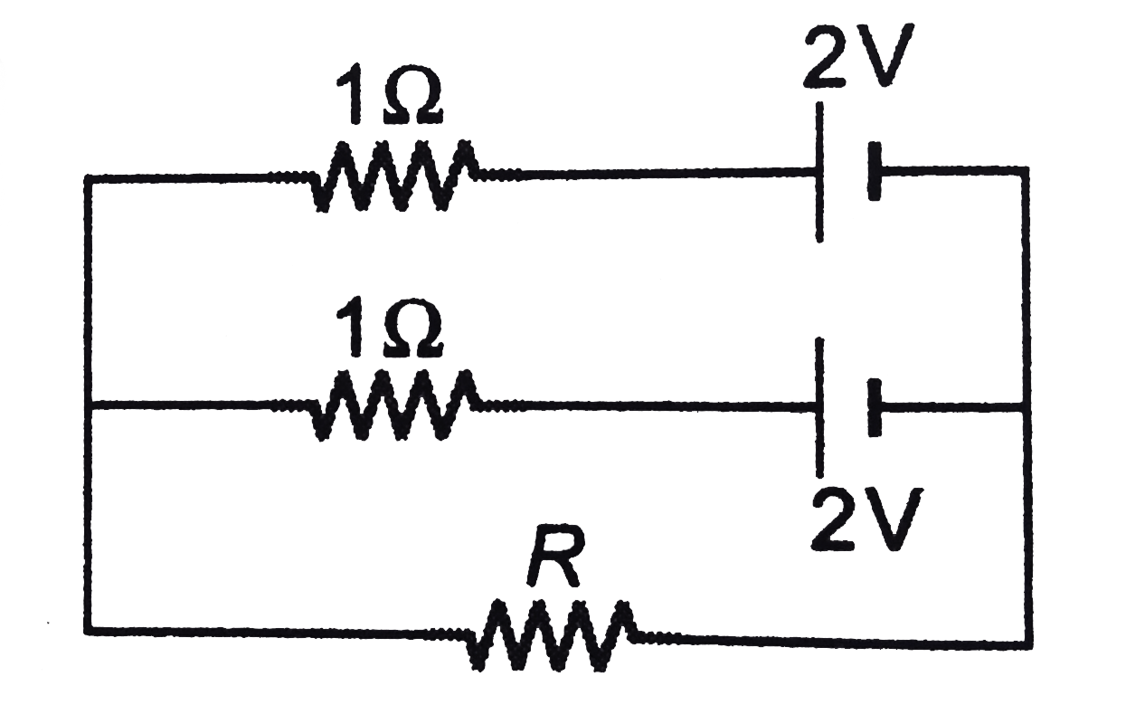
Two indentical batteries, each of emf 2V andinternal resistance r=1Ω are connected as shown. The maximum power that can be developed across R using these batteries is
 View Solution
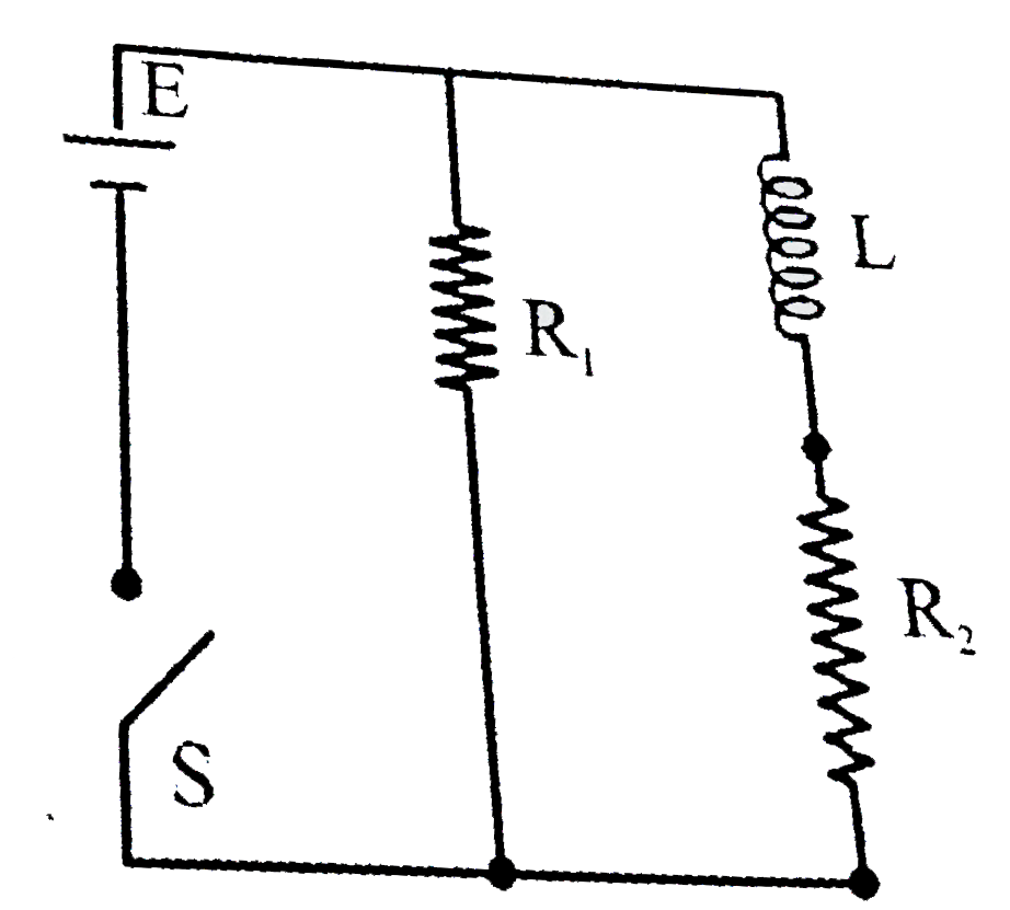
An inductor of inductance L=400mH and resistors of resistances R1=2Ω and R2=2Ω are connected to a battery of emf E=12V as shown in the figure. The internal resistance of the battery is negligible. The switch S is closed at time t=0.
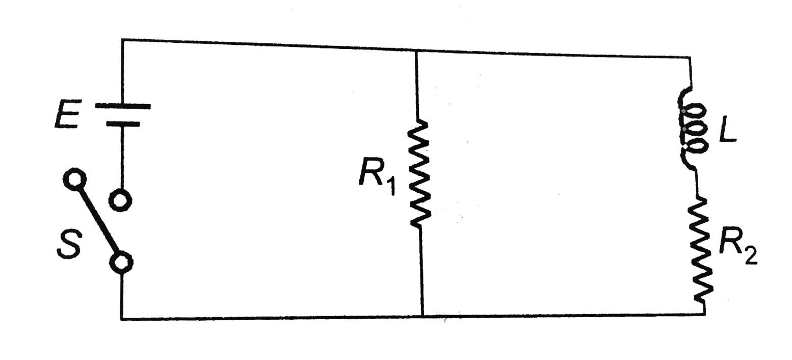
What is the potential dro across L s a function of time? After the steady state is reached, the switch is opened. What is the direction ad the magnitude of current throough R1 as a function of time?View SolutionAn inductor of inductance L = 400 mH and resistors of resistance R1=2Ω and R2=2Ω are connected to a battery of emf 12 V as shown in the figure. The internal resistance of the battery is negligible. The switch S is closed at t=0. The potential drop across L as a function of time is
 View Solution
An inductor of inductance L = 400 mH and resistors of resistance R1=2Ω and R2=2Ω are connected to a battery of emf 12 V as shown in the figure. The internal resistance of the battery is negligible. The switch S is closed at t=0. The potential drop across L as a function of time is
 View Solution

