A thin diamagnetic rod is place vertically between the poles of an electromagnet. Whenthe current in the electromagnet is switched on, then the diamagnetic rod is pushed up, out of the horizontal magnetic field. Hence, the rod gains gravitational potential energy. The work required to do this comes from
the current source
the magnetic field
the lattice structure of the material of the rod
the induced electric field due to the changing magnetic field
The correct Answer is:A
Step by step video & image solution for A thin diamagnetic rod is place vertically between the poles of an electromagnet. Whenthe current in the electromagnet is switched on, then the diamagnetic rod is pushed up, out of the horizontal magnetic field. Hence, the rod gains gravitational potential energy. The work required to do this comes from by Physics experts to help you in doubts & scoring excellent marks in Class 12 exams.
Updated on:21/07/2023Topper's Solved these Questions
- MOVING CHARGES & MAGNETISM BOOK - VMC MODULES ENGLISHCHAPTER - MOVING CHARGES & MAGNETISM EXERCISE - Illustration
55 Videos
- MOVING CHARGES & MAGNETISM BOOK - VMC MODULES ENGLISHCHAPTER - MOVING CHARGES & MAGNETISM EXERCISE - SOLVED EXAMPLES
20 Videos
- MOVING CHARGES & MAGNETISM BOOK - VMC MODULES ENGLISHCHAPTER - MOVING CHARGES & MAGNETISM EXERCISE - EFFICIENT
50 Videos
- Motion in Two DimensionsBOOK - VMC MODULES ENGLISHCHAPTER - Motion in Two DimensionsEXERCISE - MCQ
2 Videos
- PROPERTIES OF MATTERBOOK - VMC MODULES ENGLISHCHAPTER - PROPERTIES OF MATTEREXERCISE - JEE Advanced (Archive) Level - 2 (MATRIX MATCH TYPE)
1 Videos
Similar Questions
A thin diamagnetic rod is placed vertically between the poles of an electromagnet. When the current in the electromagnetic is switched on, then the diamagnetic rod is pushed up, out of the horizontal magnetic field. Hence the rod gains horizontal potential energy. the work required to do this comes from
View SolutionA small rod of bismuth is suspended freely between the poles of a strong electromagnet. It is found to arrange itself at right angles to the magnetic field. This observation establishes that bismuth is
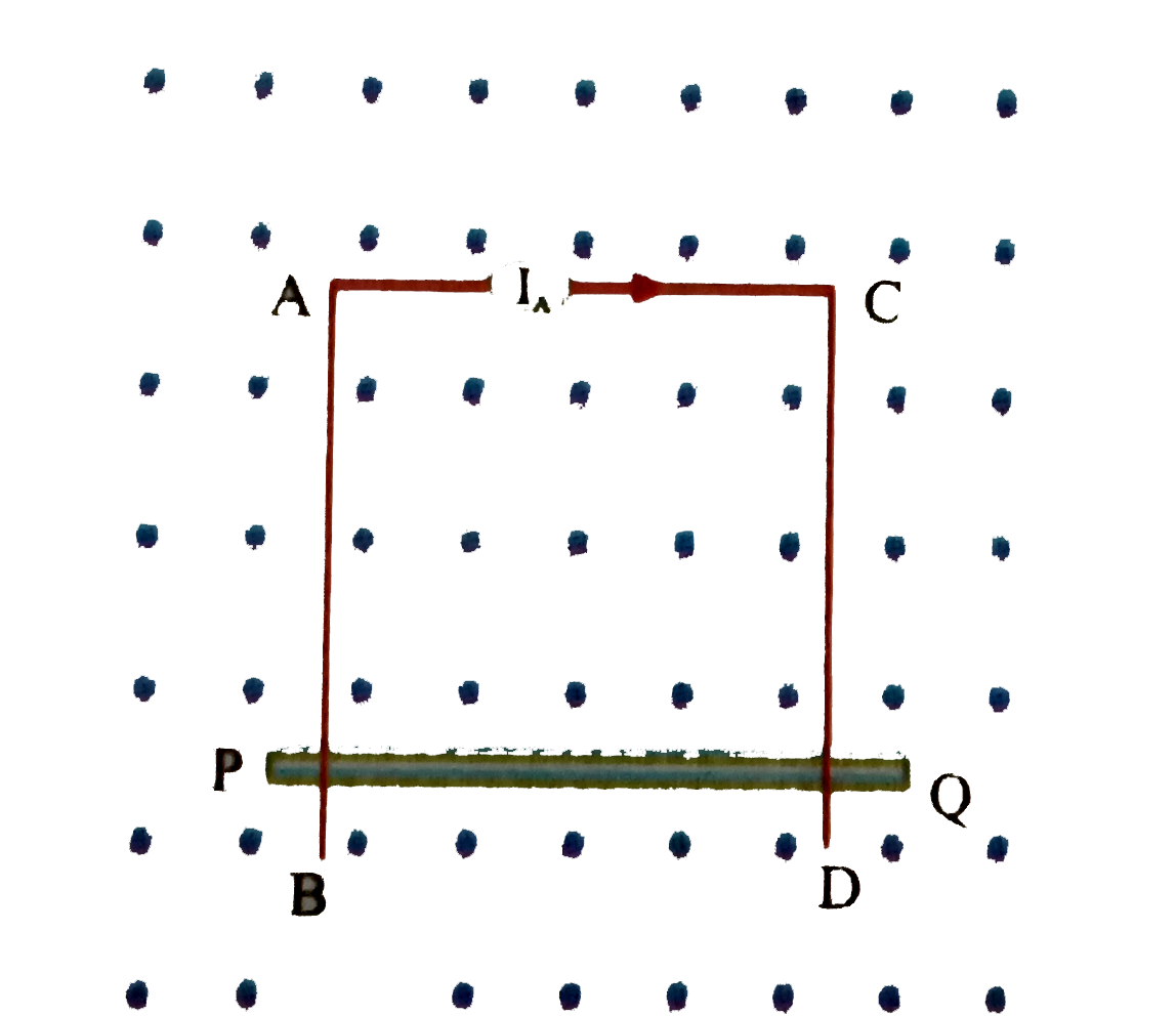
View SolutionAB and CD are fixed conducting smooth rails placed in a vertical plane and joined by a constant current source at its upper end. PQ is a conducting rod which is free to slide on the rails. A horizontal uniform magnetic field exists in space as shown in figure. If the rod PQ is released from rest then,
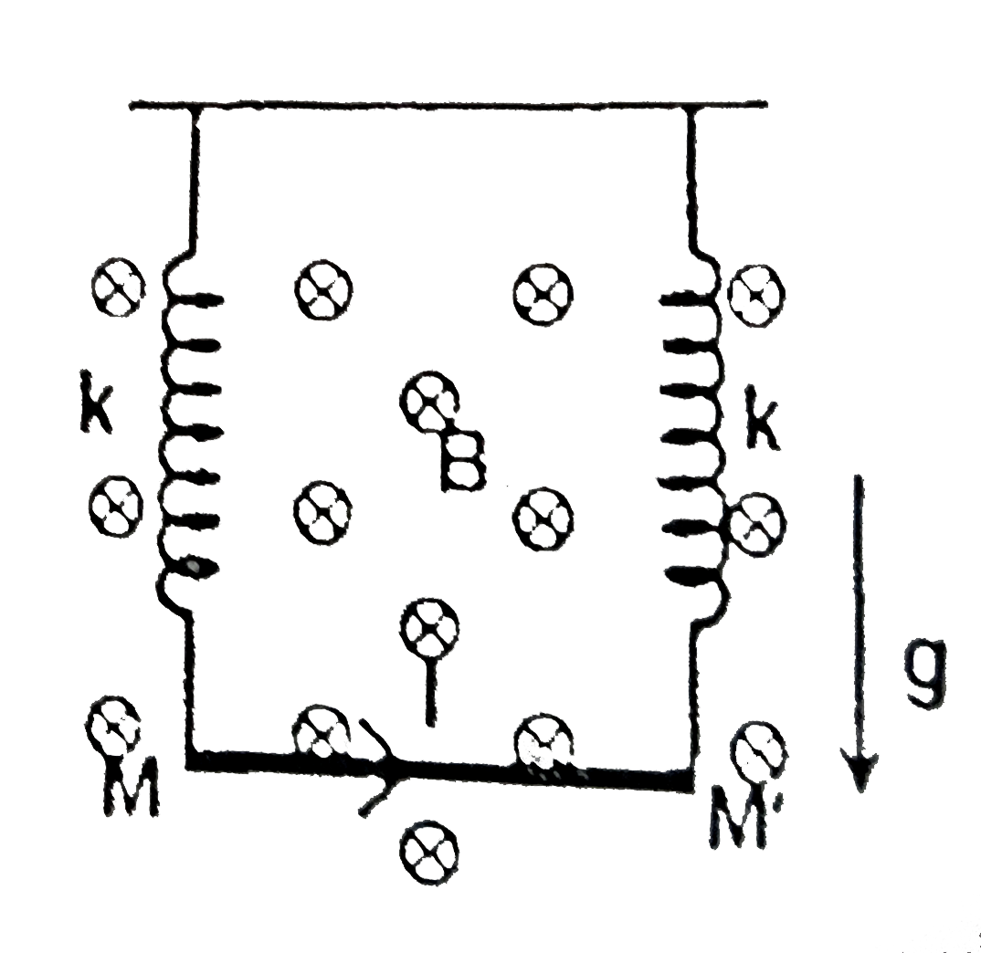
View SolutionConsider the plane of the paper to be vertical plane with direction of 'g' as shown in the figure. A rod (MM') of mass 'M' and carrying a current I. The rod is suspended vertically through two insulated spring of spring constant K at two ends. A uniform magnetic field is applied perpendicular to the plane of the paper such that the potential energy stored in the spring, in equilibrium position is zero. If the rod is slightly displaced in the vertically direction from the position of equilibrium, then the time period of oscillation is
View SolutionA conducting frame abcd is kept in a vertical plane. A conducting rod of of mass m and length l can slide smoothly on it remaining always horizontal. The resistance of the loop is negligible and inductance is constant having value L. The rod is left from rest and allowed to fall under gravity and inductor has no initial current. A magnetic field of constant magnitude Bis present throughout the loop pointing inwards. Determine
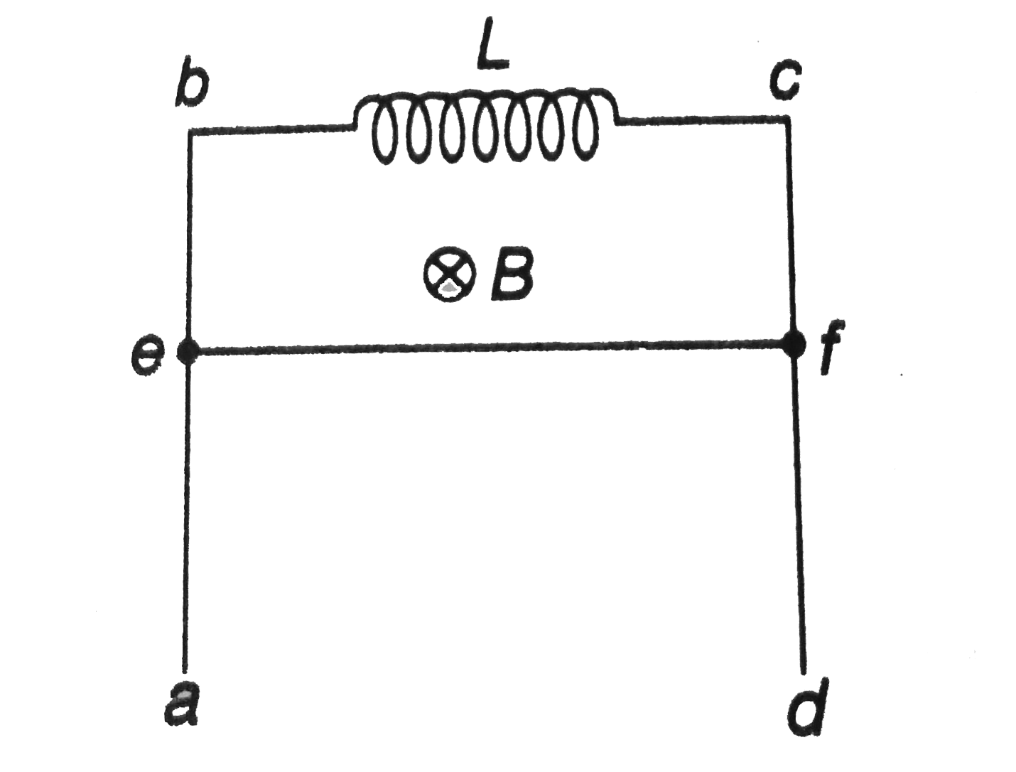
(a) position of the rod as a function of time assuming initial position of the rod to be x=0 and vertically downward as the positive x-axis.
(b) the maximum current in the circuit.
(c) maximum velocity of the rod
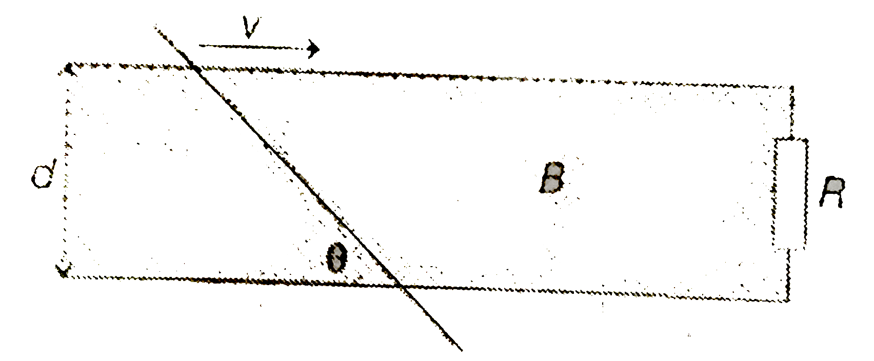
View SolutionA conducting rod with resistance r per unit length is moving inside a vertical magnetic field B with speed v on two smooth horizontal parallel ideal conducting rails. The end of the rails are connected to a resistor R. the separation between the rails is d. The rod maintains a tilted angle θ to the rail. Find the external force F required to keep the rod moving
View SolutionA conducting rod of length l slides at constant velocity v on two parallel conducting rails, placed in a uniform and constant magnetic field B perpendicular to the plane of the rails as shown in Fig.3.49. A resistance R is connected between the two ends of the rails.
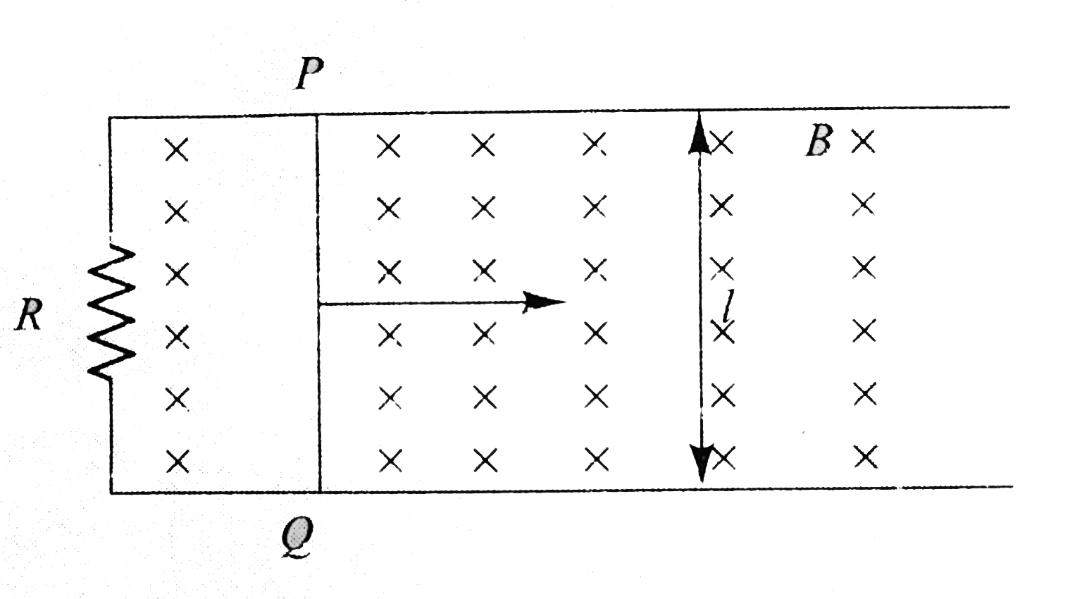
(a) Idenify the cause which produces change in magnetic flux.
(b) Identify the direction of current in the loop.
( c) Determine the emf induced in the loop.
(d) Compute the electric power dissipated in the resistor.
(e) Calcualte the mechenical power required to pull the rod at a cinstant velovity.
View SolutionA non-conducting ring of mass m and radius R has a charge Q uniformly distributed over its circumference. The ring is placed on a rough horizontal surface such that plane of the ring is parallel to the surface. A vertical magnetic field B=B0t2 tesla is switched on. After 2 a from switching on the magnetic field the ring is just about to rotate about vertical axis through its centre.
(a) Find friction coefficient μ between the ring and the surface.
(b) If magnetic field is switched off after 4s, then find the angle rotated by the ring before coming to stop after switching off the magnetic field.
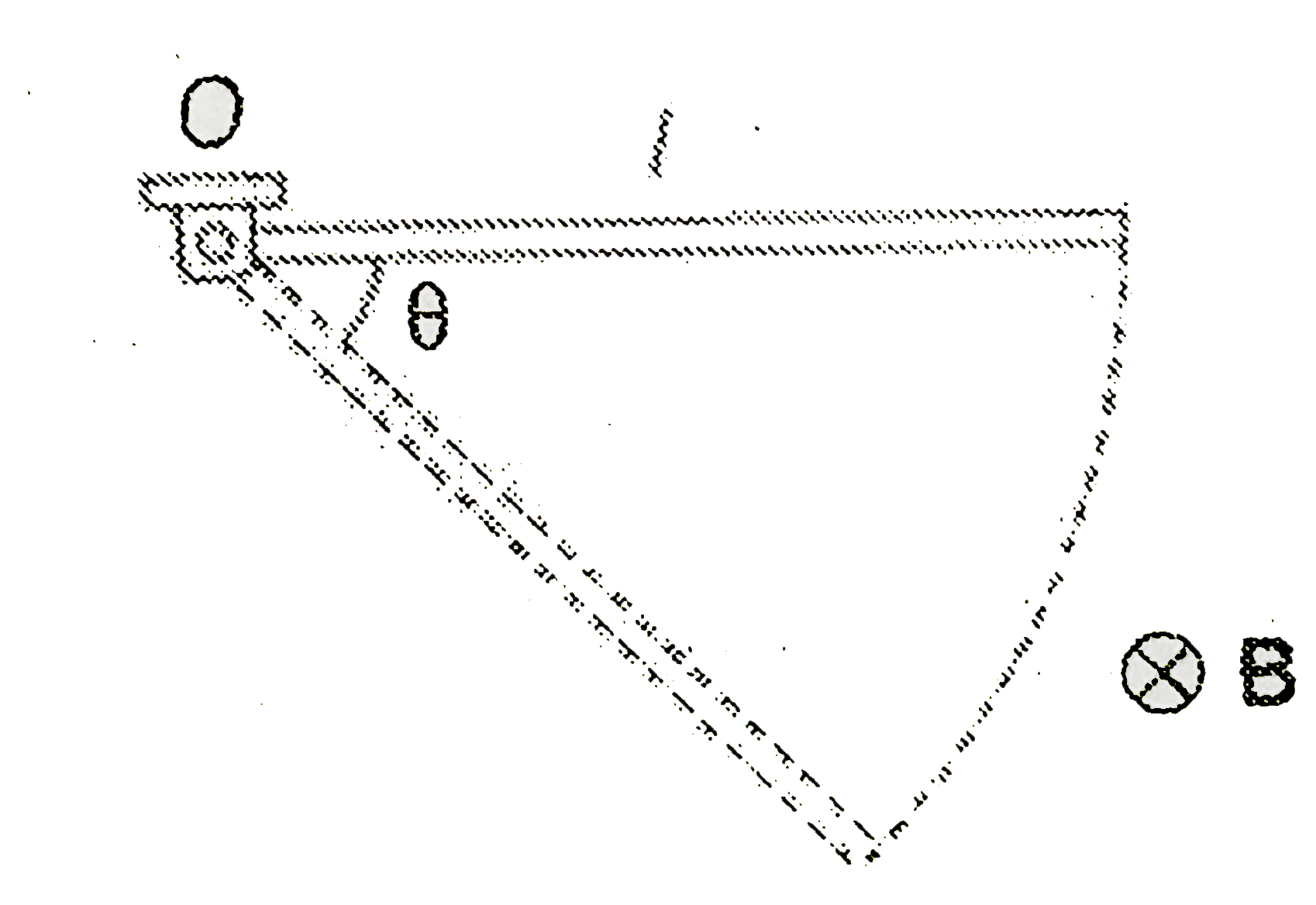
View SolutionA conducting rod of length l is hinged at point O. It is a free to rotate in a verical plane. There exists a uniform magnetic field B in horizontal direction. The rod is released from the position shown. The potential difference between the two ends of the rod is proportional to
View SolutionA straight horizontal conducting rod of length 0⋅45m and mass 60g is suspended by two vertical wires at its end. A current of 5⋅0A is set up in the rod through the wires. (a) What magnetic field should be set up normal to the conductor inorder that the tension in the wires is zero? (b) What will be the total tension in the wires if the direction of current is reversed, keeping the magnetic field same as before. (Ignore the mass of the wire) g=9⋅8ms−2.
View Solution
