If a voltmeter, in advertently mistaken for an ammeter, were inserted into the circuit, the current
increases
remains same
decreases
becomes zero
The correct Answer is:3
To solve the problem, we need to analyze the effect of mistakenly inserting a voltmeter into a circuit in place of an ammeter. Here’s a step-by-step solution:
Step 1: Understand the Circuit Configuration
Initially, we have a circuit with a voltage source (V) and a resistor (R). An ammeter (with low resistance, RA) is connected in series to measure the current flowing through the circuit.
Step 2: Calculate the Current with the Ammeter
Using Ohm's Law, the total resistance in the circuit when the ammeter is connected is:
Requivalent=R+RA
The current (I) flowing through the circuit can be calculated as:
I=VRequivalent=VR+RA
Step 3: Replace the Ammeter with a Voltmeter
Now, we replace the ammeter with a voltmeter (with high resistance, RV). The new total resistance in the circuit becomes:
R′equivalent=R+RV
Step 4: Analyze the Resistance Values
Since the resistance of the voltmeter (RV) is very high compared to the resistance of the ammeter (RA), we can conclude:
R′equivalent>Requivalent
This means that the equivalent resistance of the circuit has increased when the voltmeter is used instead of the ammeter.
Step 5: Calculate the New Current
The new current (I′) in the circuit with the voltmeter can be calculated as:
I′=VR′equivalent=VR+RV
Step 6: Compare the Currents
Since R′equivalent>Requivalent, it follows that:
I′<I
This indicates that the current has decreased when the voltmeter is used in place of the ammeter.
Conclusion
Therefore, the current in the circuit decreases when a voltmeter is mistakenly inserted instead of an ammeter.
Final Answer
The current would decrease.
---
Initially, we have a circuit with a voltage source (V) and a resistor (R). An ammeter (with low resistance, RA) is connected in series to measure the current flowing through the circuit.
Using Ohm's Law, the total resistance in the circuit when the ammeter is connected is:
Requivalent=R+RA
The current (I) flowing through the circuit can be calculated as:
I=VRequivalent=VR+RA
Now, we replace the ammeter with a voltmeter (with high resistance, RV). The new total resistance in the circuit becomes:
R′equivalent=R+RV
Since the resistance of the voltmeter (RV) is very high compared to the resistance of the ammeter (RA), we can conclude:
R′equivalent>Requivalent
This means that the equivalent resistance of the circuit has increased when the voltmeter is used instead of the ammeter.
The new current (I′) in the circuit with the voltmeter can be calculated as:
I′=VR′equivalent=VR+RV
Since R′equivalent>Requivalent, it follows that:
I′<I
This indicates that the current has decreased when the voltmeter is used in place of the ammeter.
Therefore, the current in the circuit decreases when a voltmeter is mistakenly inserted instead of an ammeter.
The current would decrease.
Topper's Solved these Questions
- MOVING CHARGES & MAGNETISM BOOK - VMC MODULES ENGLISHCHAPTER - MOVING CHARGES & MAGNETISM EXERCISE - PRACTICE EXERCISE 7
5 Videos
- MOVING CHARGES & MAGNETISM BOOK - VMC MODULES ENGLISHCHAPTER - MOVING CHARGES & MAGNETISM EXERCISE - PRACTICE EXERCISE 8
5 Videos
- MOVING CHARGES & MAGNETISM BOOK - VMC MODULES ENGLISHCHAPTER - MOVING CHARGES & MAGNETISM EXERCISE - PRACTICE EXERCISE 5
5 Videos
- Motion in Two DimensionsBOOK - VMC MODULES ENGLISHCHAPTER - Motion in Two DimensionsEXERCISE - MCQ
2 Videos
- PROPERTIES OF MATTERBOOK - VMC MODULES ENGLISHCHAPTER - PROPERTIES OF MATTEREXERCISE - JEE Advanced (Archive) Level - 2 (MATRIX MATCH TYPE)
1 Videos
Similar Questions
The ammeter reading in the given circuit is
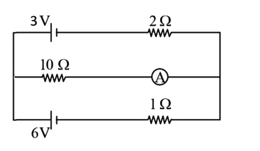
View SolutionThe reading of ammeter in the circuit is
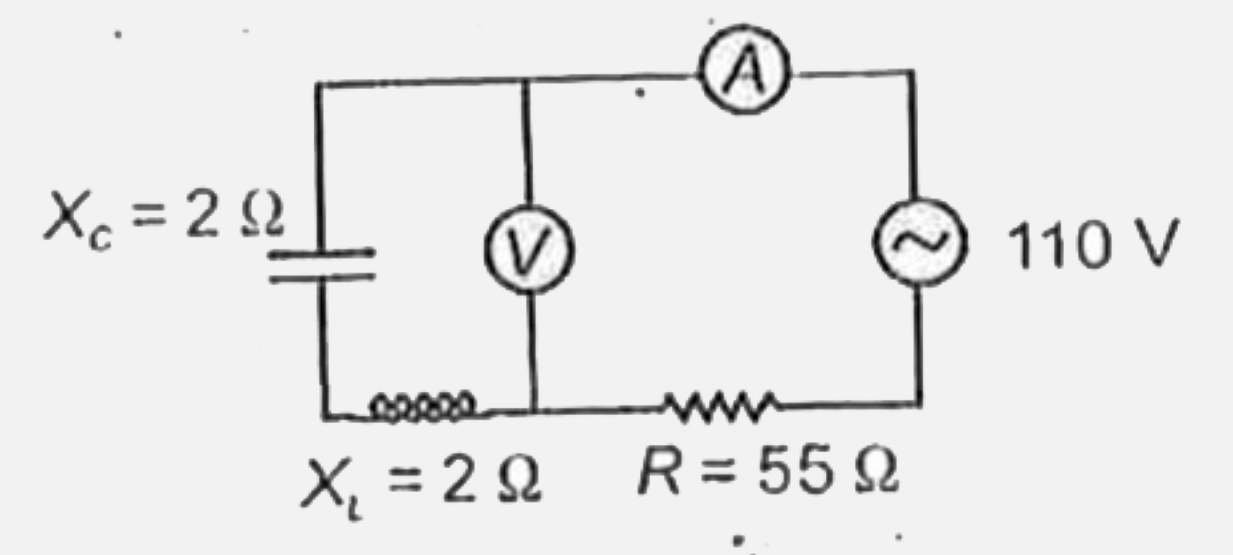
View SolutionAn ideal voltmeter V and ideal ammeter A are connected in a circuit as shown in the figure. If the reading of the voltmeter is 32 V, the reading of ammeter will be
View SolutionVoltmeter V and Ammeter A are used to measure the total potential difference of the circuit and the current through each resistor. Which is the correct circuit ?
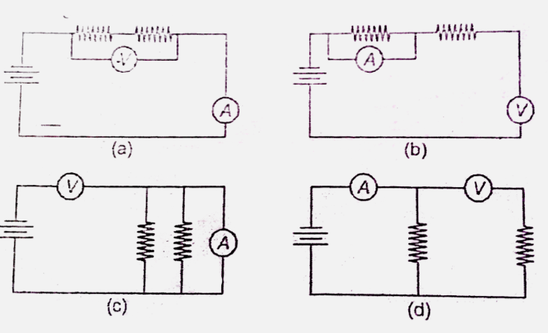
View SolutionThe reading of the ideal ammeter in the circuit is
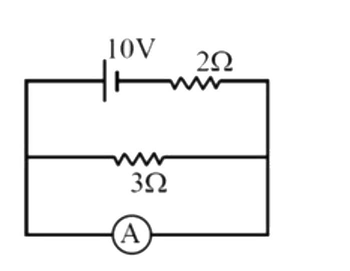
View SolutionThe reading of ammeter and voltmeter in the given circuit is
_PHY_E06_306_Q01.png)
View SolutionWhy is ammeter connected in series and voltmeter in parallel in the circuit?
View SolutionShown two ideal voltmeters and an ammeter, which are connected across the various circuit elements. If the voltmeter connected across 9Ω resistance reads 4.5 V, then answer the following problems.
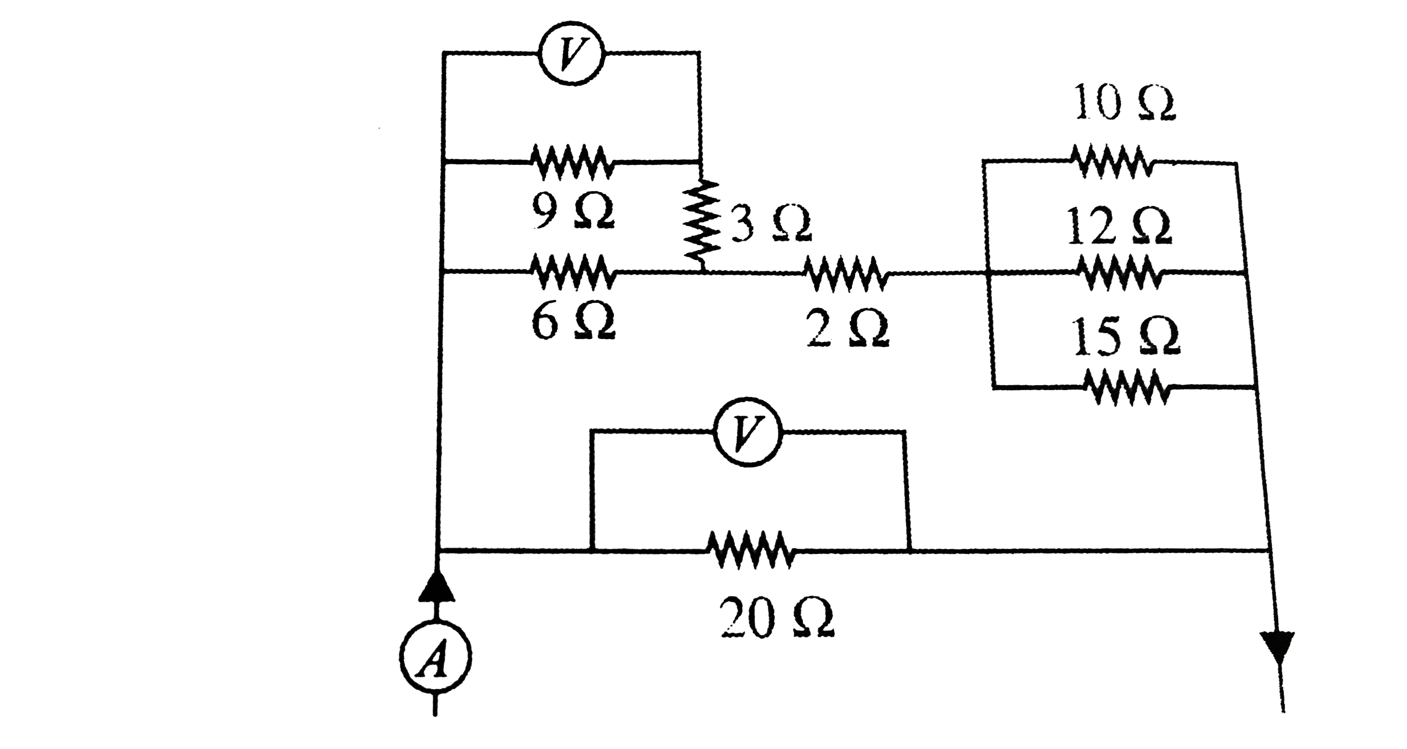
The reading of the ammeter is
View SolutionShown two ideal voltmeters and an ammeter, which are connected across the various circuit elements. If the voltmeter connected across 9Ω resistance reads 4.5 V, then answer the following problems.
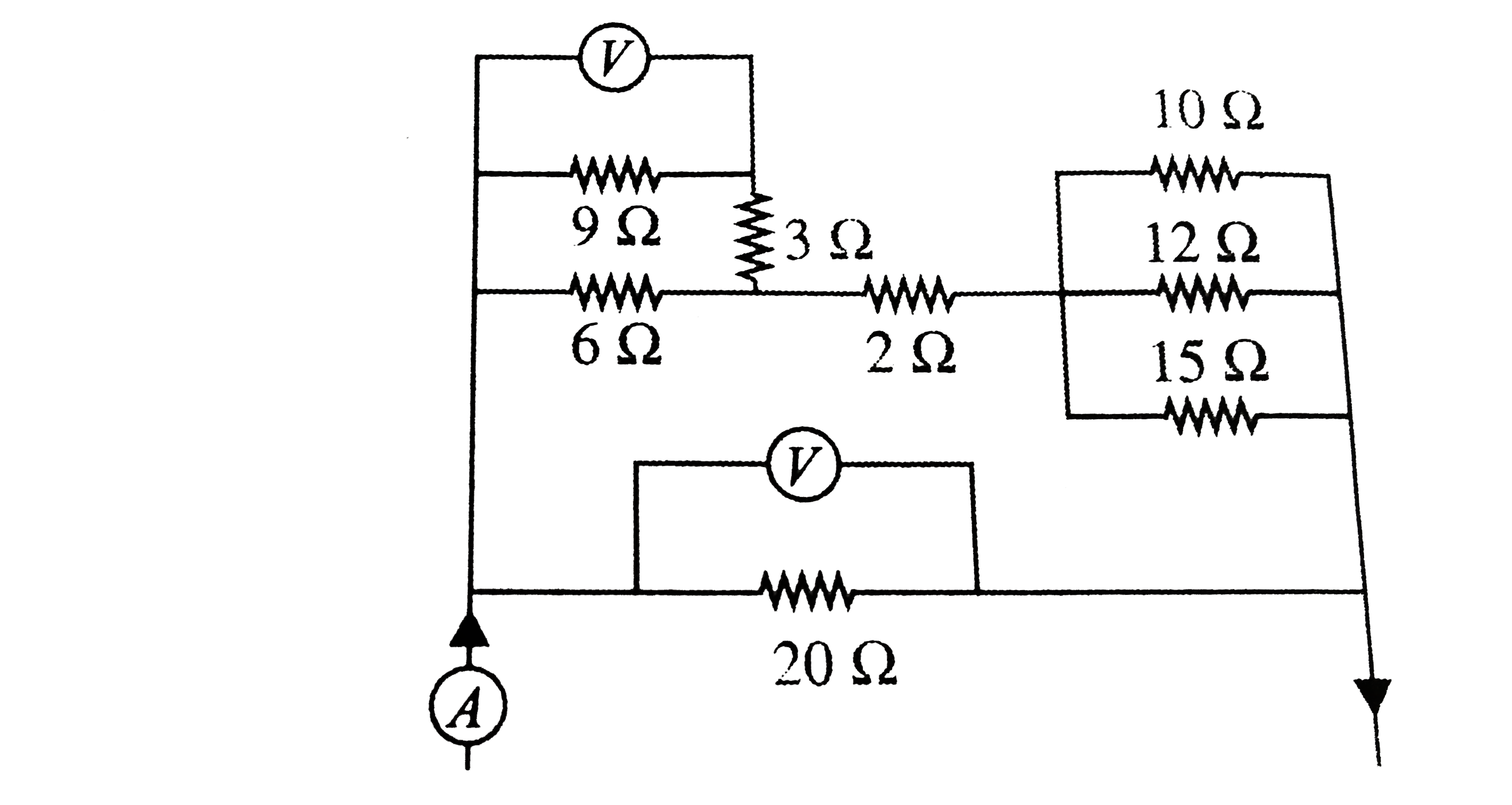
The current through 12Ω resistance is
View SolutionA student connects a voltmeters, ammeter and resistance according to the circuit given. If the voltmeter reading is 20V and ammeter reading is 4A, then the resistance will be

View Solution
