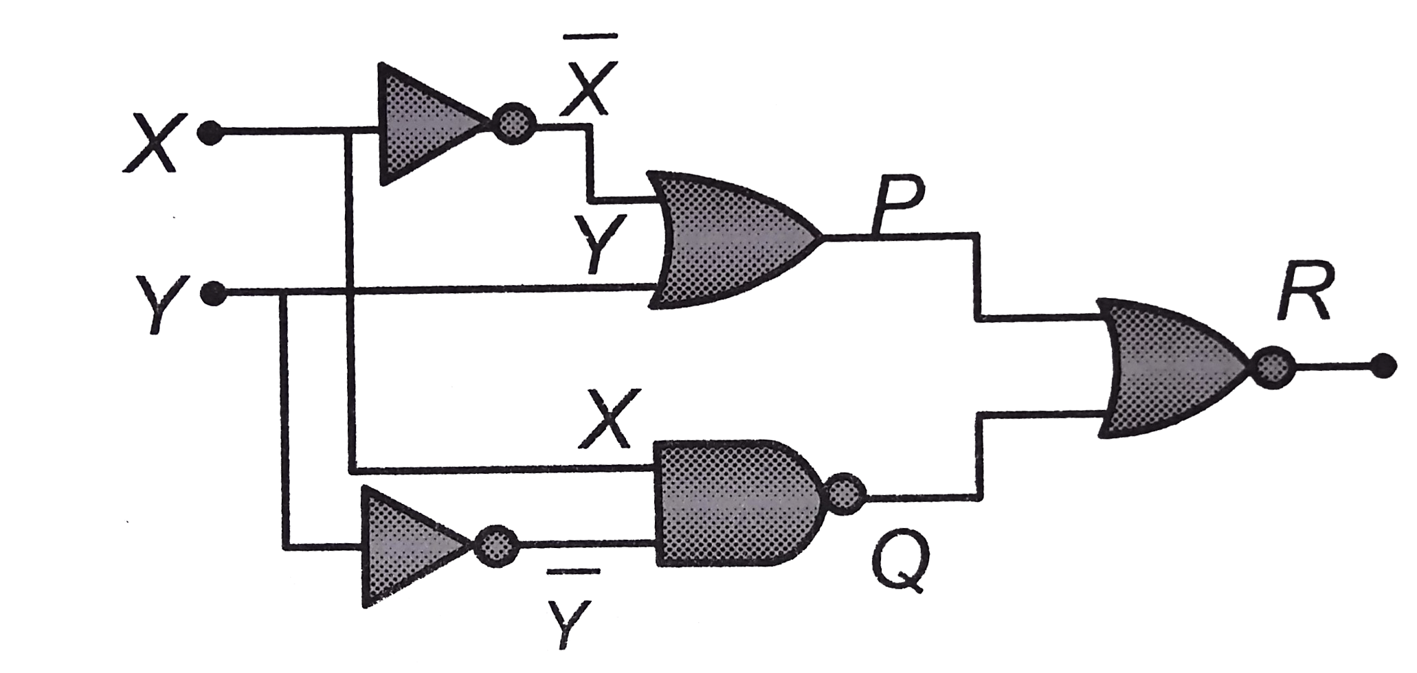
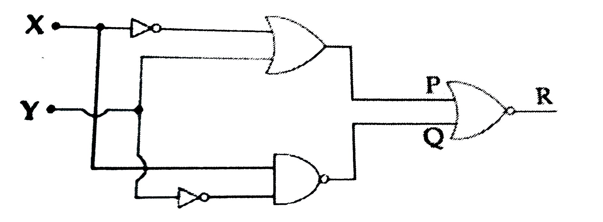
Figure gives a system of logic gates. From the study of truth table it can be found that no produce a high output (1) at R, we must have
X=0,Y=1
X=1, Y=1
X=1, Y=0
X=0, Y=0
The correct Answer is:C
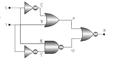
The truth table cab be written as

Hence, X = 1, Y =0 gives output R = 1
Topper's Solved these Questions
Similar Questions
To which logic gate does the truth table given in the figure correspond?
View SolutionThe arrangement given below represents a logic gate:

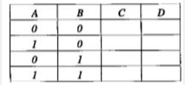
Copy the following truth table in your answer booklet and complete it showing outputs at C and D
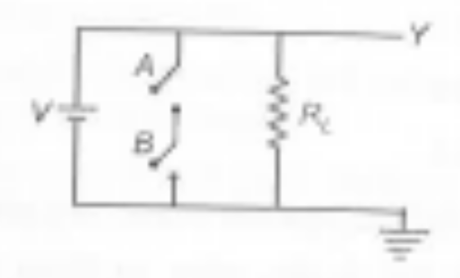
View SolutionThe logic gate realised from the circuit as shown in the figure is (A and B are inputs and Y is output)
View Solution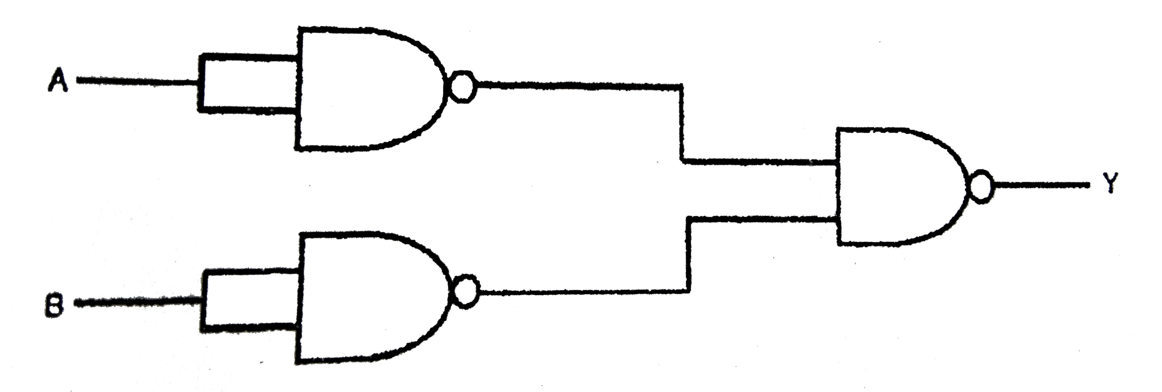
Draw the truth table for the logic gate arrangement shown in the figure.
View SolutionTruth table for system of four NAND gates as shown in figure is
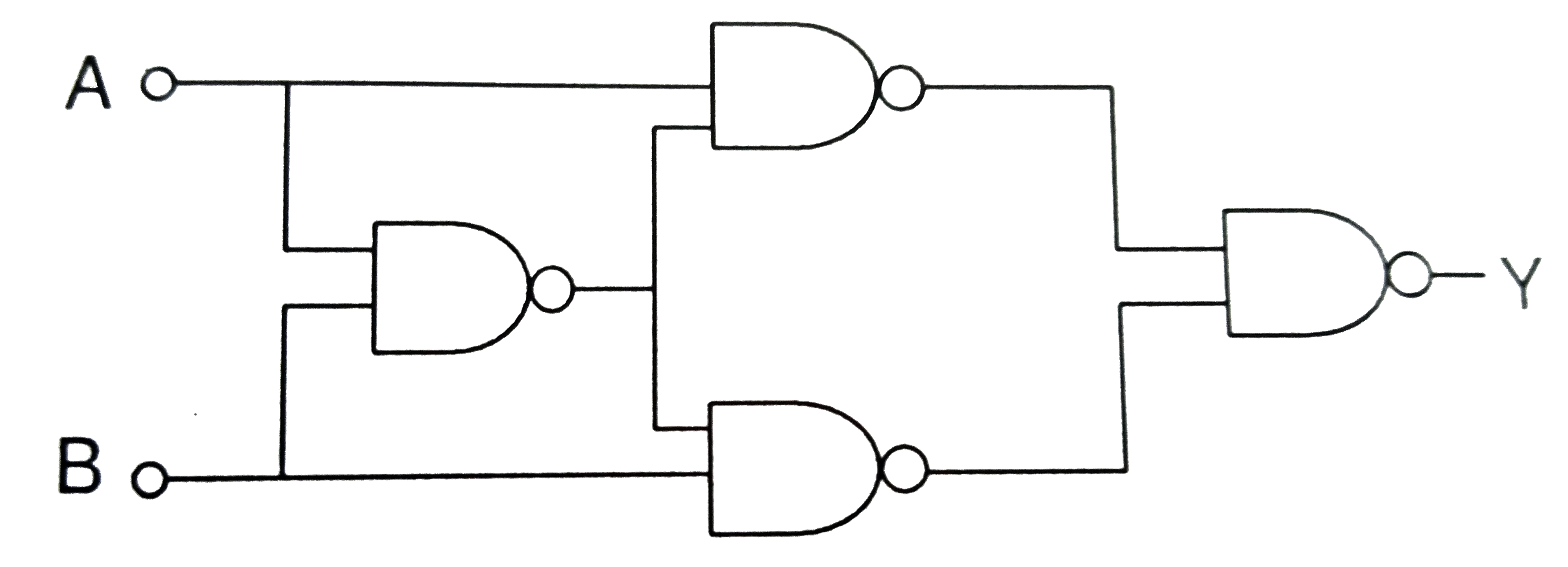
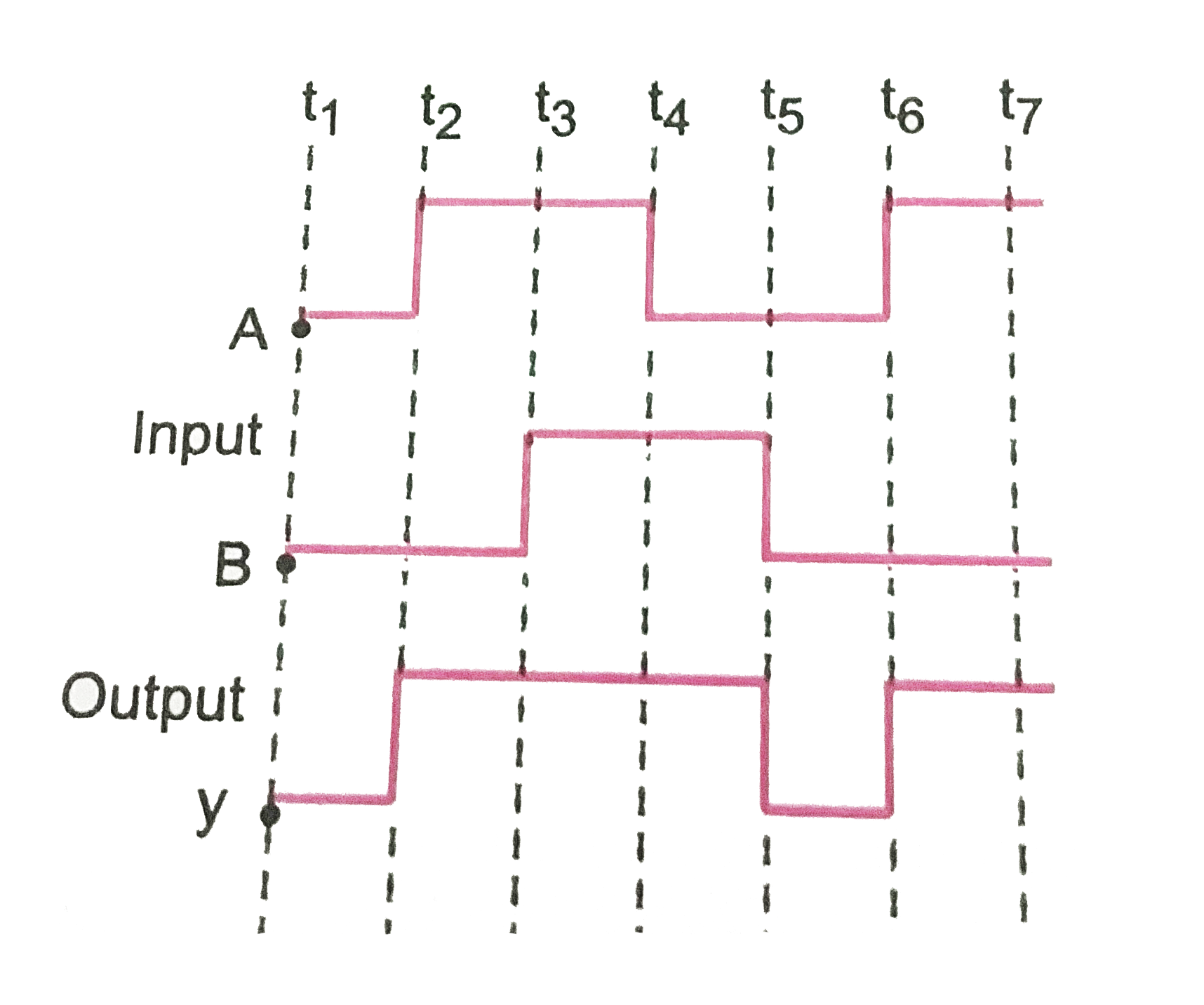
View SolutionThe Fig shown input waveforms A and B to a logic gate. Draw the output waveform for an OR gate. Write the truth table for this logic gate and draw its logic symbol.
View SolutionIt is required to design a (two -input) logic gate, using an appropriate number, of :
(a) NAND gates that gives a 'low' output only when both the inputs are 'low'.
(b) NOR gates that gives a 'high' output only when both the inputs are 'high'.
Draw the logic circuits for these two cases and write the truth table, corresponding to each of the two designs.
View SolutionConsider the situatioin shown in figure. The system is released from rest and the block of mass 1.0 kg is found to have a speed 0.3 m/s ater it has descended thrugh a distance of 1 m. find the coefficient of kinetic friction between the block and the table.
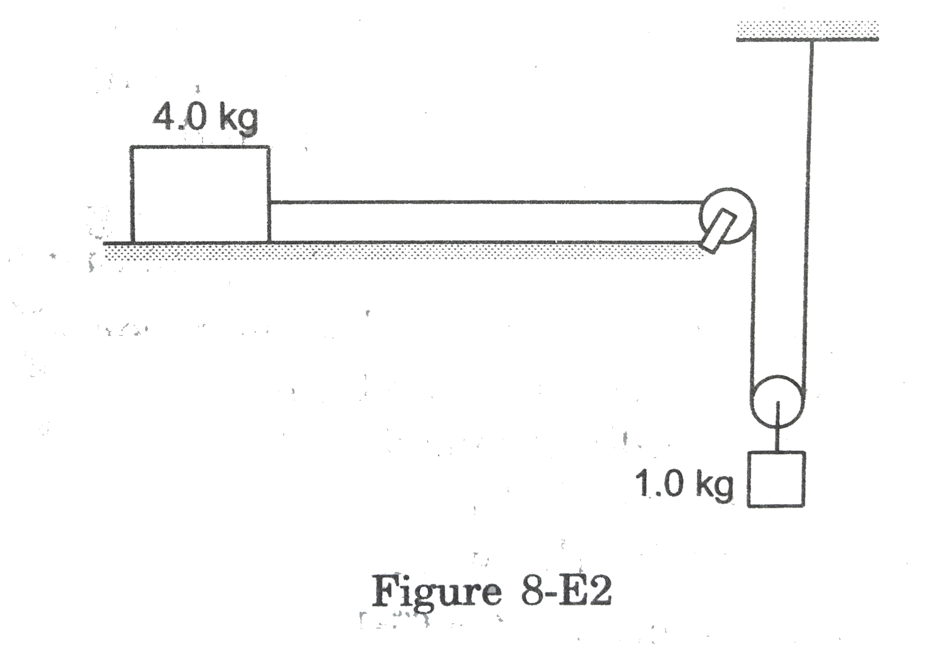
View SolutionTo get output '1' at R, for the given logic gate circuit the input values must be :
View SolutionIdentify the gates P and Q shown in the figure. Write the truth table for the combination of the gates shown.

Name the equivalent gate representing this circuit and write its logic symbol.
View Solution
