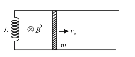
As shown in figure, the two parallel conducting rails, in a horizontal plane, are connected at one end by an inductor of inductance L. A slider (metallic) of mass m, is imparted a Velocity v0, upon the rails, as shown in figure. The period of oscillation of the conducting rod is
π2√mLBl
2π√mL3Bl
2π√mLBl
3π√mL2Bl
The correct Answer is:C
Step by step video & image solution for As shown in figure, the two parallel conducting rails, in a horizontal plane, are connected at one end by an inductor of inductance L. A slider (metallic) of mass m, is imparted a Velocity v_(0), upon the rails, as shown in figure. The period of oscillation of the conducting rod is by Physics experts to help you in doubts & scoring excellent marks in Class 12 exams.
Updated on:21/07/2023Similar Questions
A conducting rod of length L slides at a constant velocity V on two parallel conducting rails as shown in figure. The mechanical power required to pull the rod at constant velocity is

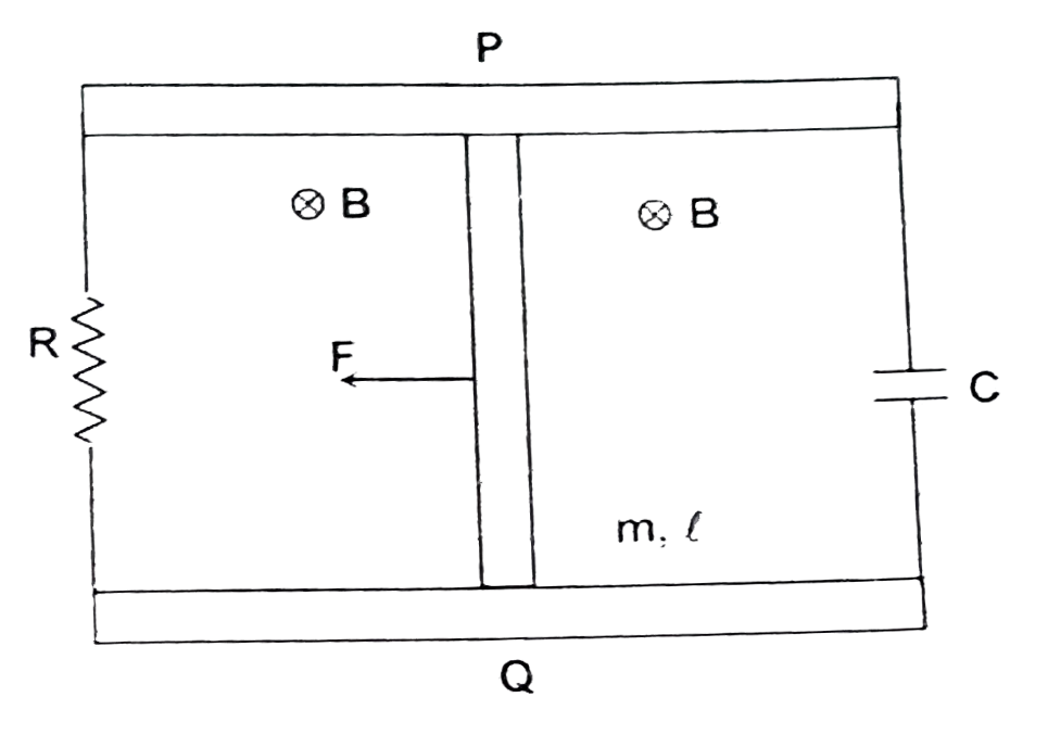
View SolutionTwo smooth horizontal parallel conducting rails are connected with a capacitor and a resistor at the two ends as shown. A uniform conducting rod PQ of mass 'm' and length 'l' is dragged with a constant horizontal force 'F'. The terminal velocity aquired by the conducting rod is
View SolutionIn the shown figure, there are two long fixed parallel conducting rails (having negligible resistance) and are separated by distance L. A uniform rod of resistance R and mass M is placed at rest on frictionless rails. Now at time t=0, a capacitor having charge Q0 and capacitance C is connected across rails at ends a and b such that current in rod (cd) is from c towards d and the rod is released. A uniform and constant magnetic field having magnitude B exists normal to plane of paper as shown. (Neglect acceleration due to gravity)
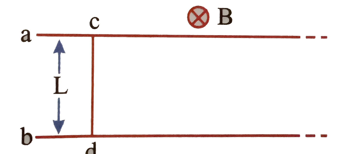
When the speed of rod is v, the charge on capacitor is :
View SolutionIn the shown figure, there are two long fixed parallel conducting rails (having negligible resistance) and are separated by distance L.A uniform rod of resistance R and mass M is placed at rest on frictionless rails. Now at time t = 0, a capacitor having charge Q0 and capacitance C is connected across rails at ends a and b such that current in rod(cd) is from c towards d and the rod is released. A uniform and constant magnetic field having magnitude B exists normal to plane of paper as shown. (Neglect acceleration due to gravity)
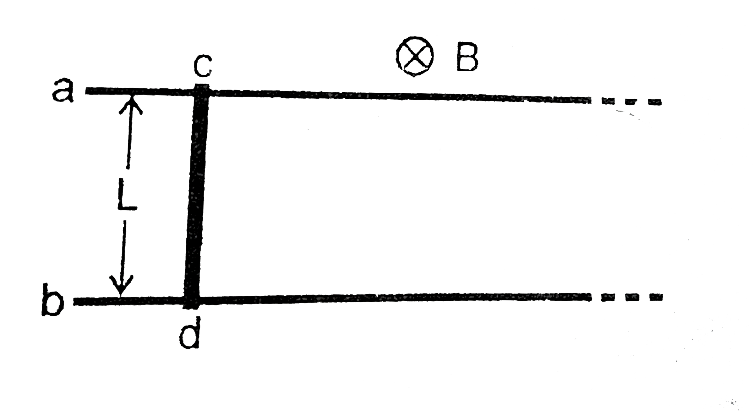
When the acceleration of rod is zero, the speed of rod is :
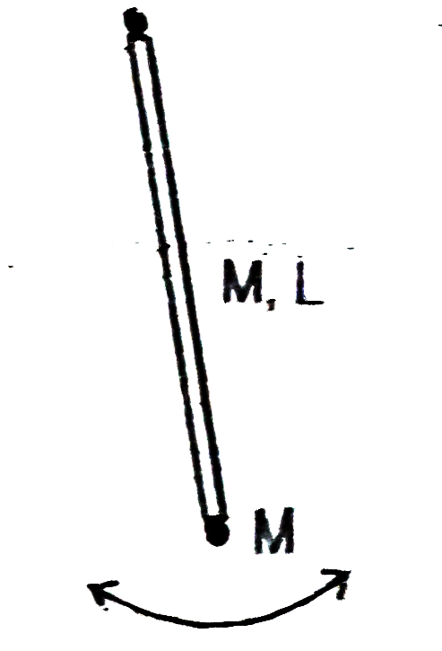
View SolutionA uniform rod ofmass M and length L is hanging from its one end free to rotate in a veritcal plane.A small ball of equal mass is attached of the lowe end as shown. Time period of small oscillations of the rod is
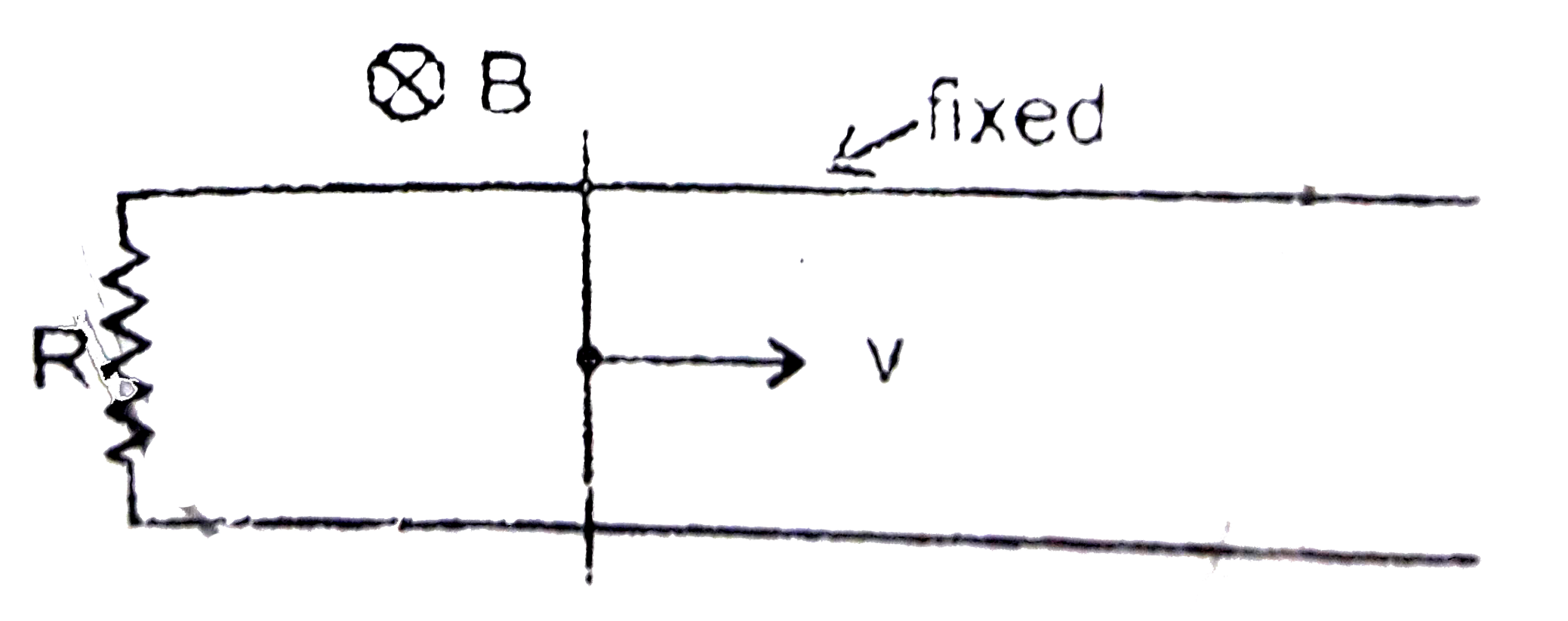
View SolutionA resistance R is connected between the two ends of the parallel smooth conducting rails.A conducting rod lies on these fixed horizontal rails and a uniform constant magnetic field B exists perpendicular to the plane of the rails as shown in the figure.If the rod is given a velocity v and released as shown in figure, it will stop after some time, which option are correct:
View Solution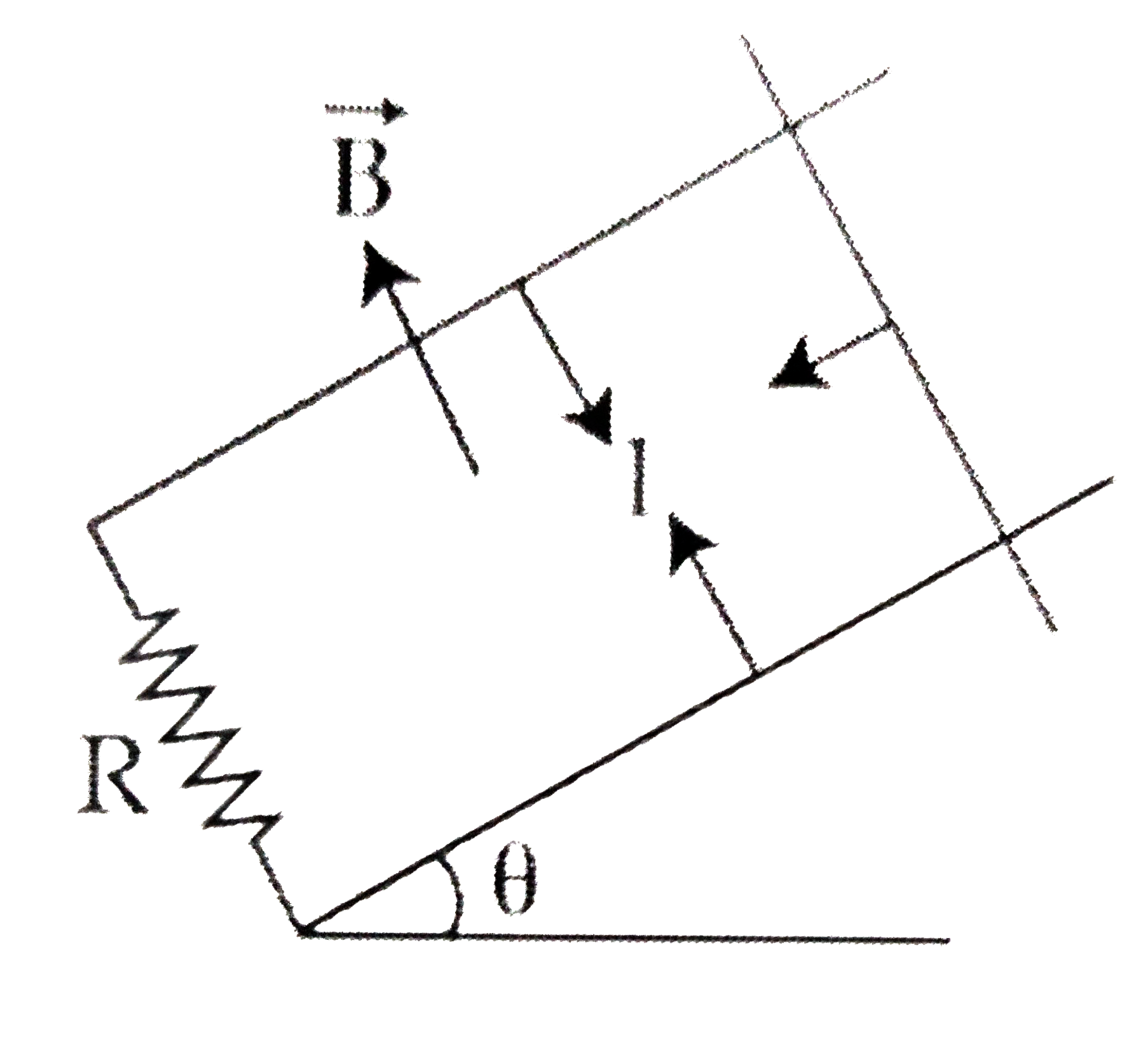
a copper rod of mass m slides under gravity on two smooth parallel rails with separation I and set at an angle of θ with the horiziontal at the bottom rails are joined by resistance R. There is a uniform magnetic field B normal to the plane of the rails as shown in the figure The terminal speed of the copper rod is :
View SolutionTwo long parallel horizontal rails a, a distance d aprt and each having a risistance λ per unit length are joing at one end by a resistance R. A perfectly conduction rod MN of mass m is free to slide along the rails without friction (see figure). There is a uniform magnetic field of induction B normal to the plane of the paper and directed into the paper. A variable force F is applied to the rod MN such that, as the rod moves a constant current flows through R.
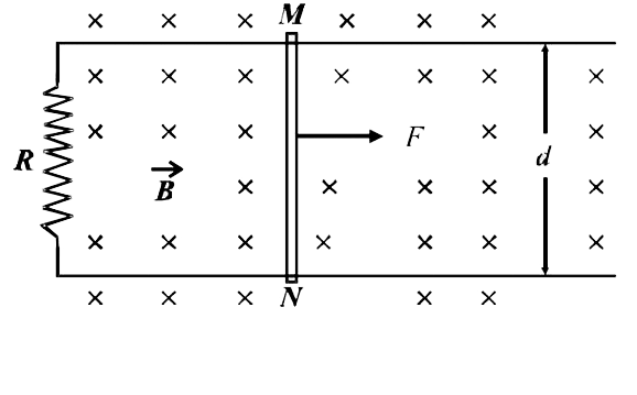
(i) Find the velocity of the rod and the applied force F as function of the distance x of the rod from R.
(ii) What fraction of the work done per second by F is converted into heat?
View Solution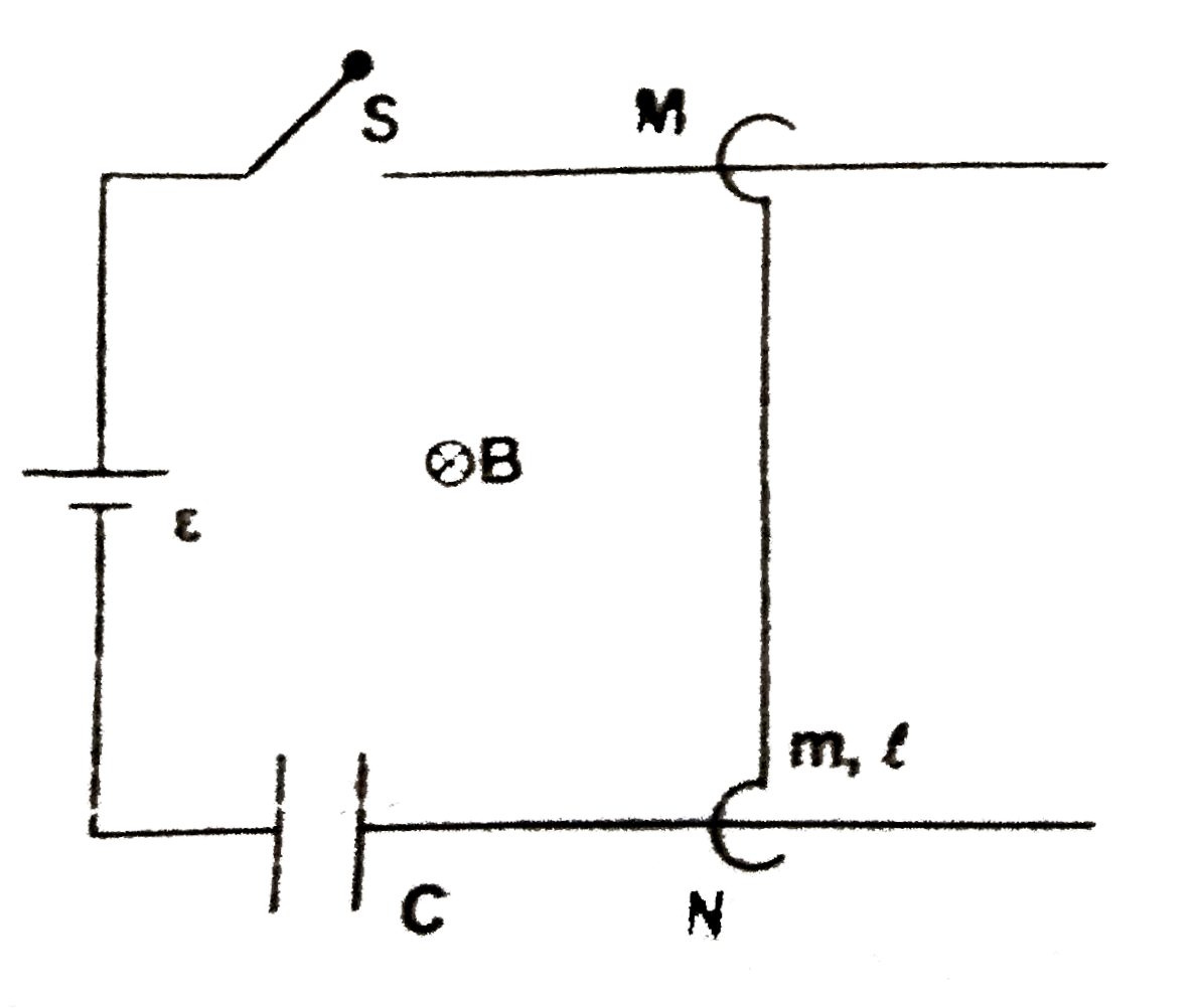
A conducting rod MN of mass m and length 'l' is placed on parallel smooth conducting rails connected to an uncharged capacitor of capacitance C and a battery of emf ε as shown. A uniform magnetic field B is existing perpendicular to the plane of the rails. The steady state velocity acquired by the conducting rod MN after closing switch S is (neglect the resistance of the parallel rails and the conducting rod)
View SolutionStatement I: A resistance R is connected between the two ends of the parallel smooth conducting rails. A conducting rod lies on these fixed horizontal rails and a uniform constant magnetic field B exists perpendicular to the plane of the rails as shown in Fig. if the rod is given a velocity υ and released as shown in Fig. 3.188, it will stop after some time. the total work done by magnetic field negative.
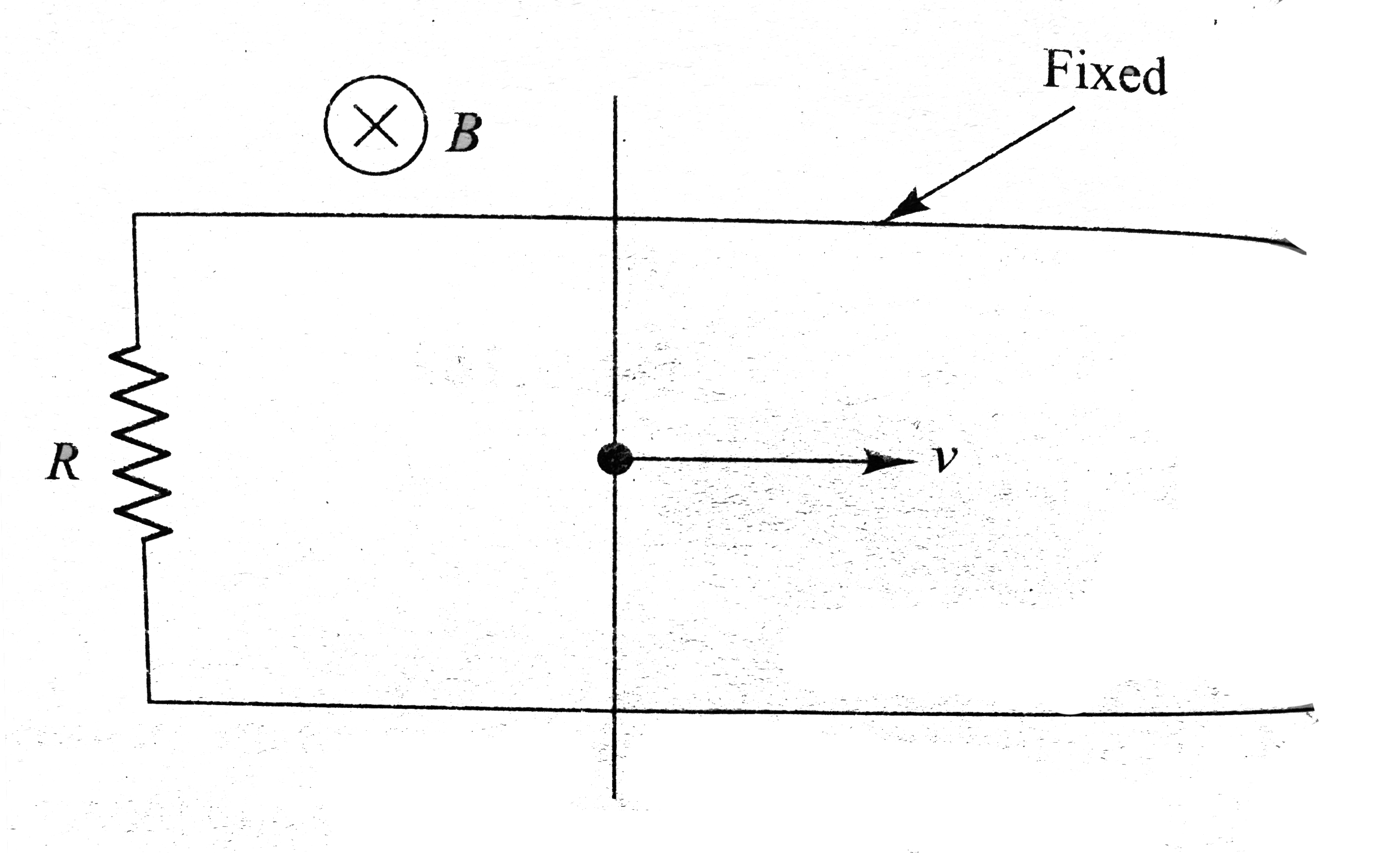
Statement II: If force acts opposite to direction of velocity its work done is negative.
View Solution
