Input waveforms A and B as shown in Fig-l are applied to the combination of gates as shown in Fig-ll. Which of the waveforms shown in Fig.(i) to (iv) correctly represents the output waveform?
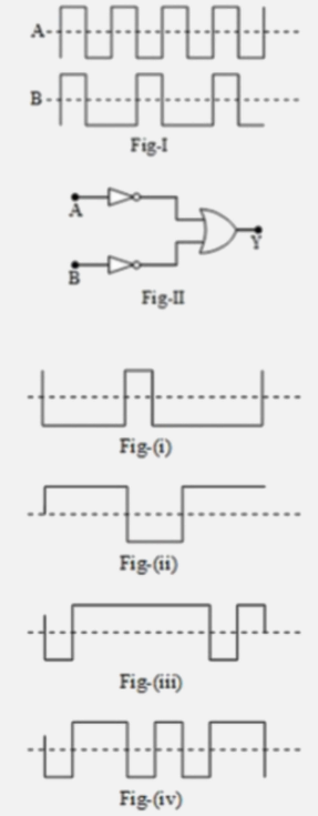
Fig .(i)
Fig .(ii)
Fig .(iii)
Fig .(iv)
The correct Answer is:C
Step by step video & image solution for Input waveforms A and B as shown in Fig-l are applied to the combination of gates as shown in Fig-ll. Which of the waveforms shown in Fig.(i) to (iv) correctly represents the output waveform? by Physics experts to help you in doubts & scoring excellent marks in Class 12 exams.
Updated on:21/07/2023Similar Questions
The combination of the gates shown represents :-
_E01_431_Q01.png)
View SolutionThere are two coils A and B as shown in Fig.
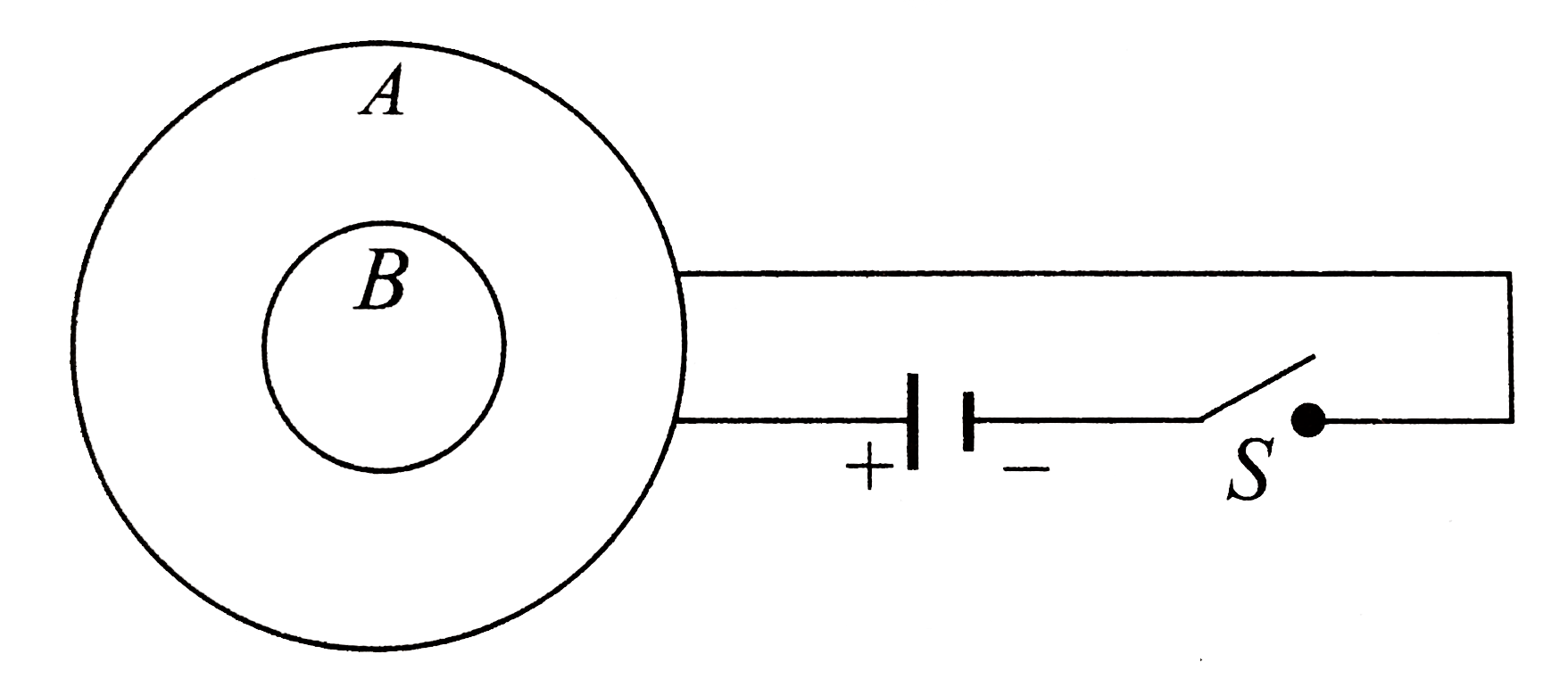
View SolutionThe output Y of the combination of logic gates shown is equal to
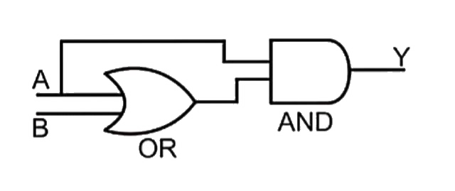
View SolutionFind the focal length of the lens shown in Fig.
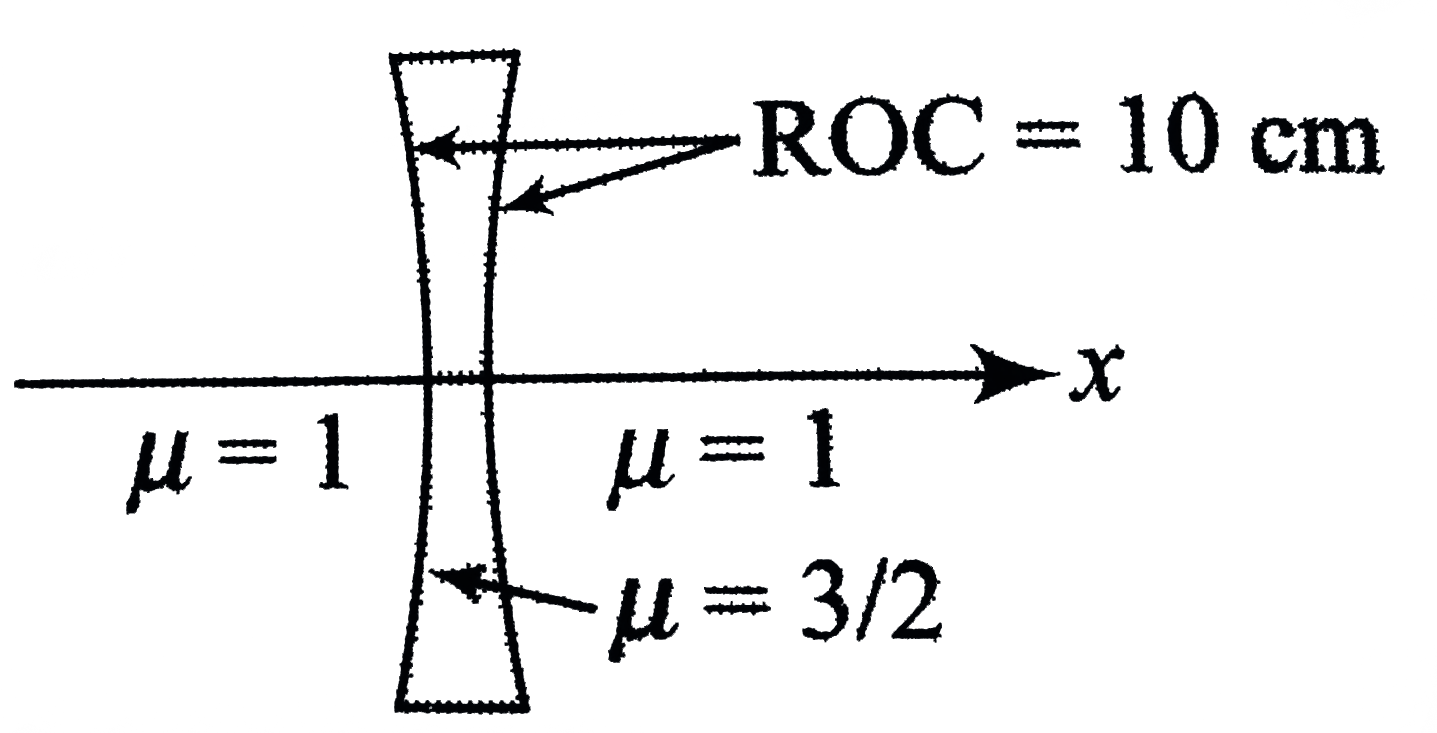
View Solution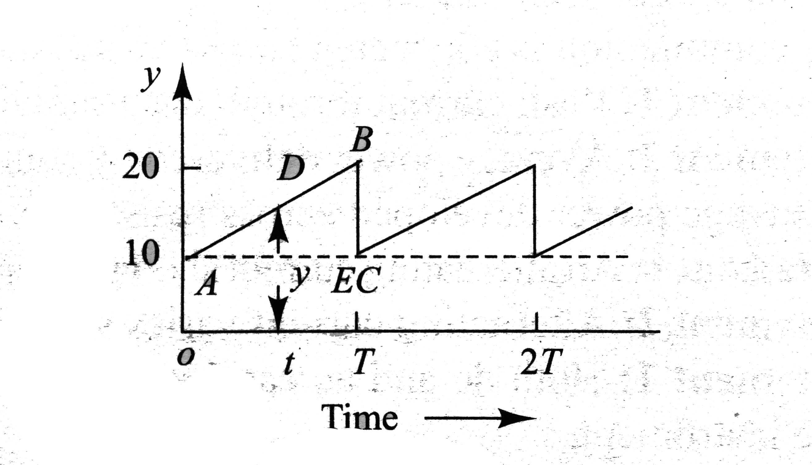
the average value of the wave-from shown in fig. is
View SolutionAn amplitude modulated wave is as shown in Fig.
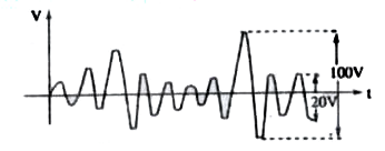
Which of the following is/are correct ?
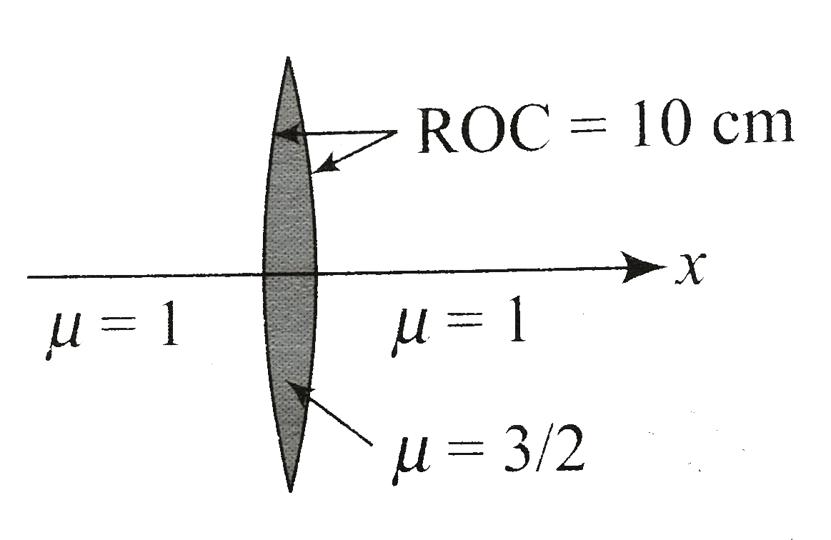
View SolutionFind the focal length of the lens shown in the Fig..
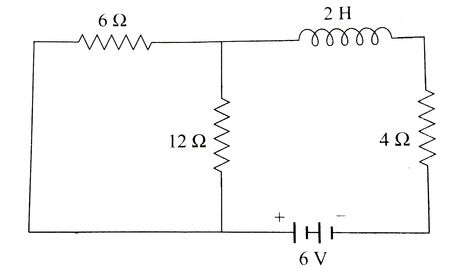
View SolutionFor the circuit shown in Fig. Which of the following statements are correct?
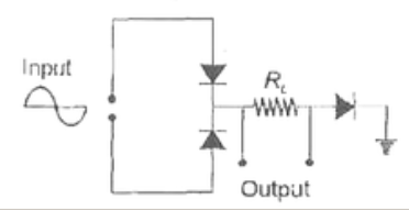
View SolutionIn the circuit shown , the input waveform is given. Which of the following correctly gives the output wavefrorm across RL?
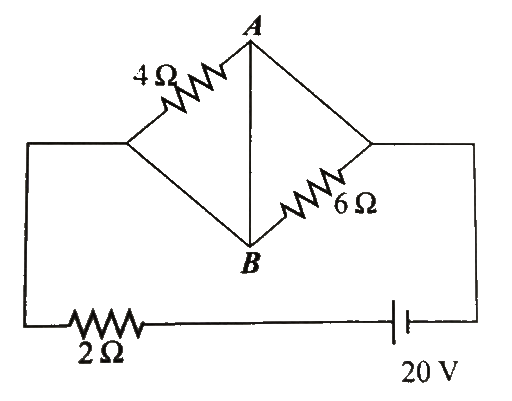
View SolutionIn the circuit shown in Fig. 7.45,
View Solution
