A Zener diode is connected to a battery and a load as shown below. The currents and are respectively :-
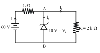
12.5 mA, 7.5 mA, 5 mA
15 mA, 7.5 mA, 7.5 mA
12.5 mA, 5 mA, 7.5 mA
15 mA, 5 mA, 10 mA
The correct Answer is:A
Step by step video & image solution for A Zener diode is connected to a battery and a load as shown below. The currents l, l_(Z) and l_(L) are respectively :- by Physics experts to help you in doubts & scoring excellent marks in Class 12 exams.
Updated on:21/07/2023Similar Questions
Knowledge Check
The + l-effect is shown by
ACH3B−OHCFD−C6H5
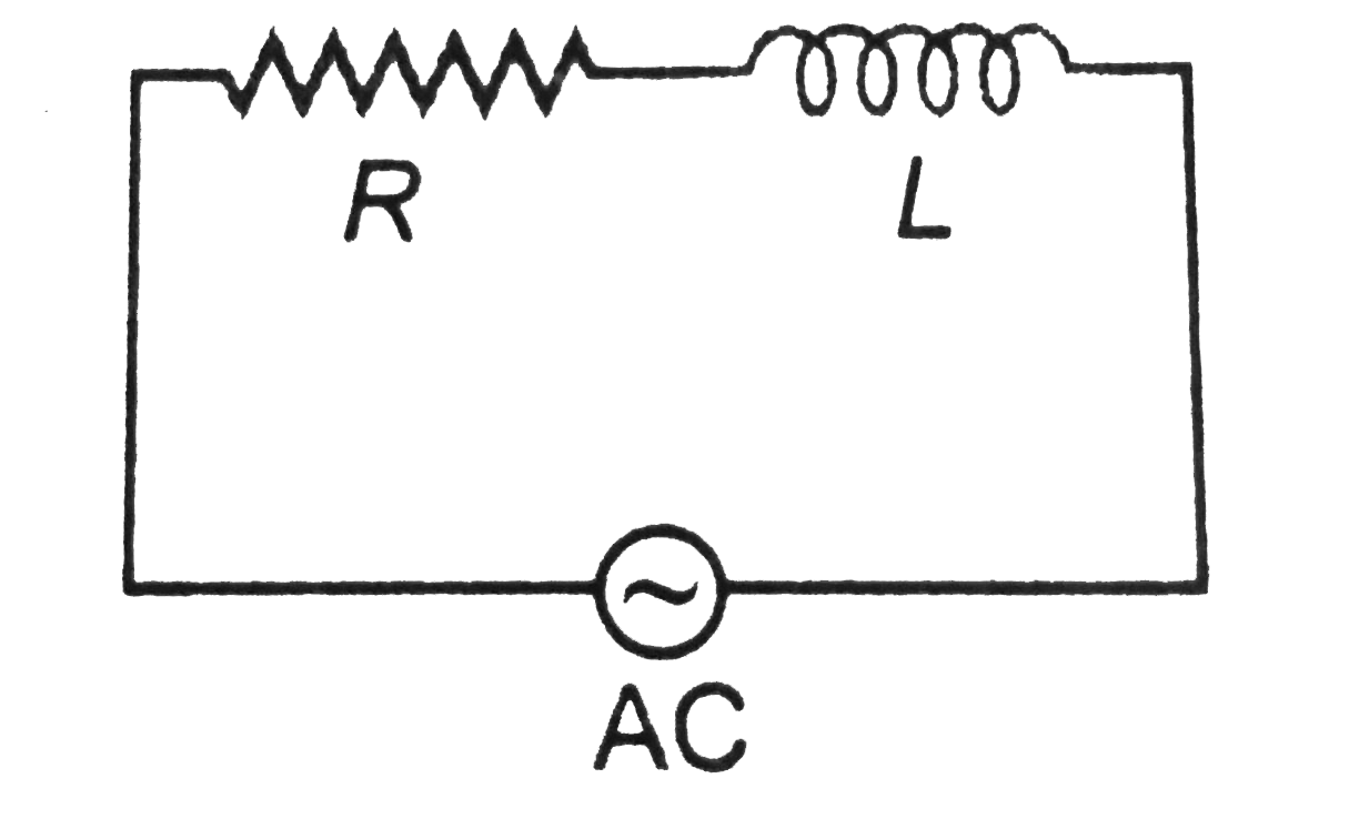
A circuit contains resistance R and an inductance L in series. An alternating voltage V=V0sinωt is applied across it. The currents in R and L respectively will be
 .
.
View SolutionA circuit contains resistance R and an inductance L in series. An alternating voltage V=V0sinωt is applied across it. The currents in R and L respectively will be
 .
.
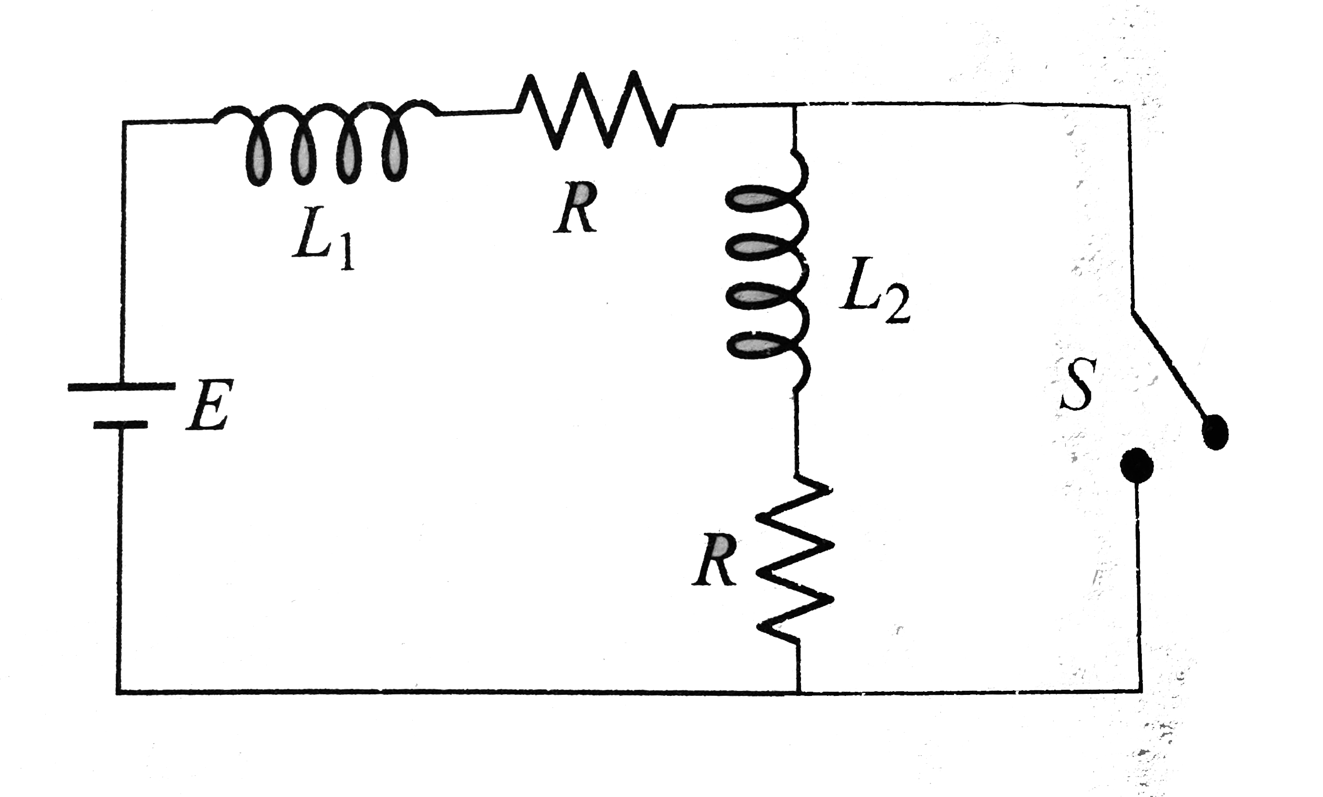
View SolutionSwitch S shown in Fig. is closed for t<0 and is opened at t=0. When currents through L1 and L2 are equal, their common value is
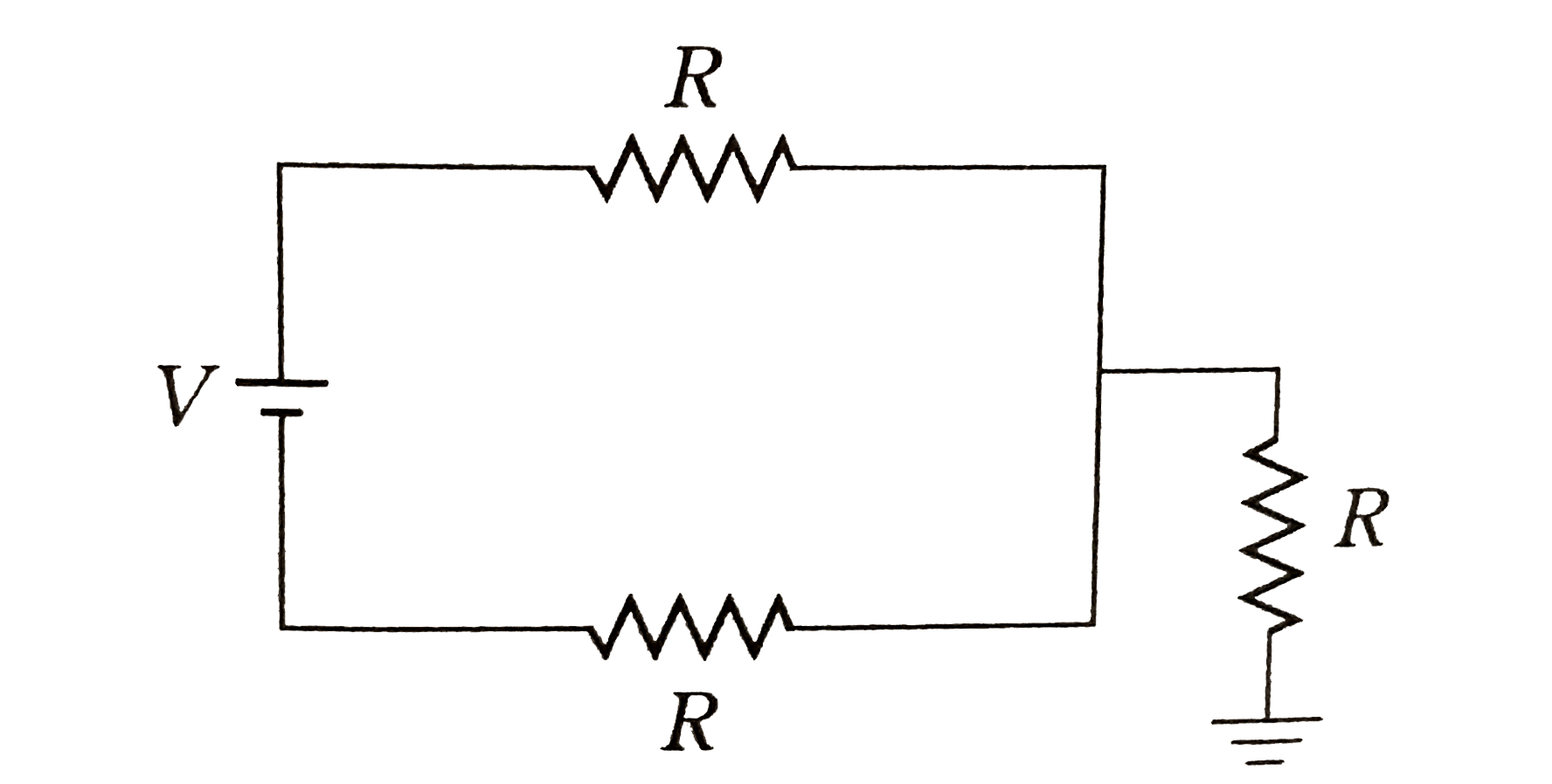
View SolutionThe current drawn from the battery shown in the figure is l =
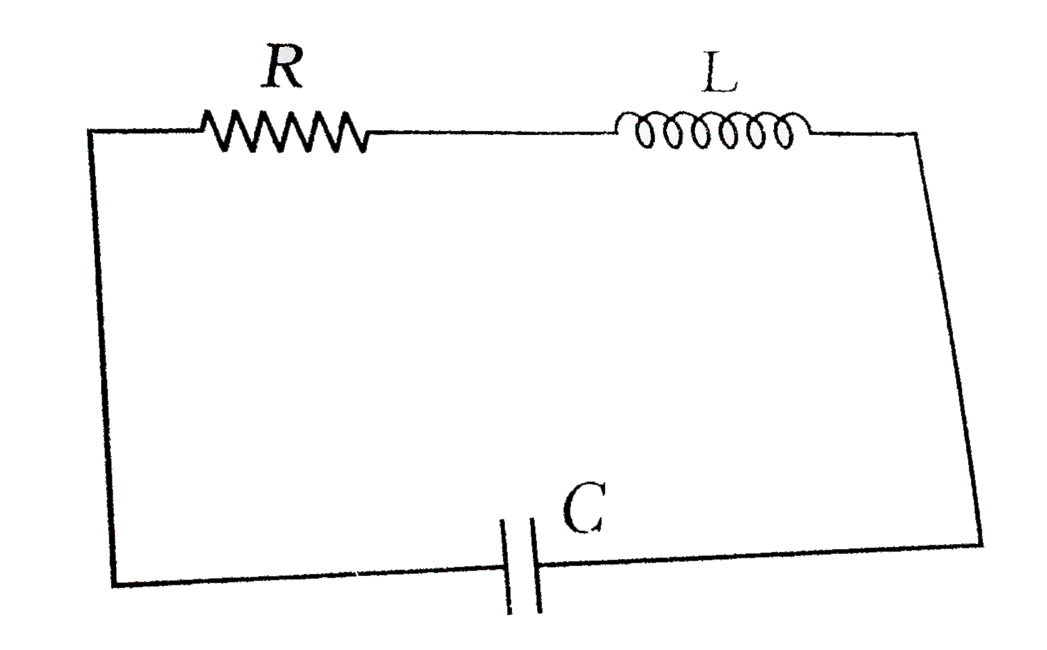
View SolutionA L-C-R circuit is equivalent to a damped pendulum . In an L-C-R circuit the capacitor is charged to Qo and then connected to the L and R as shown below.
If a student plots graph of the square of maximum charge on the capacitor with time (t) for two different values L1 and L2 (L1gtL2of L), then which of the following represents this graph correctly (plots are schematic and not drawn to scale)
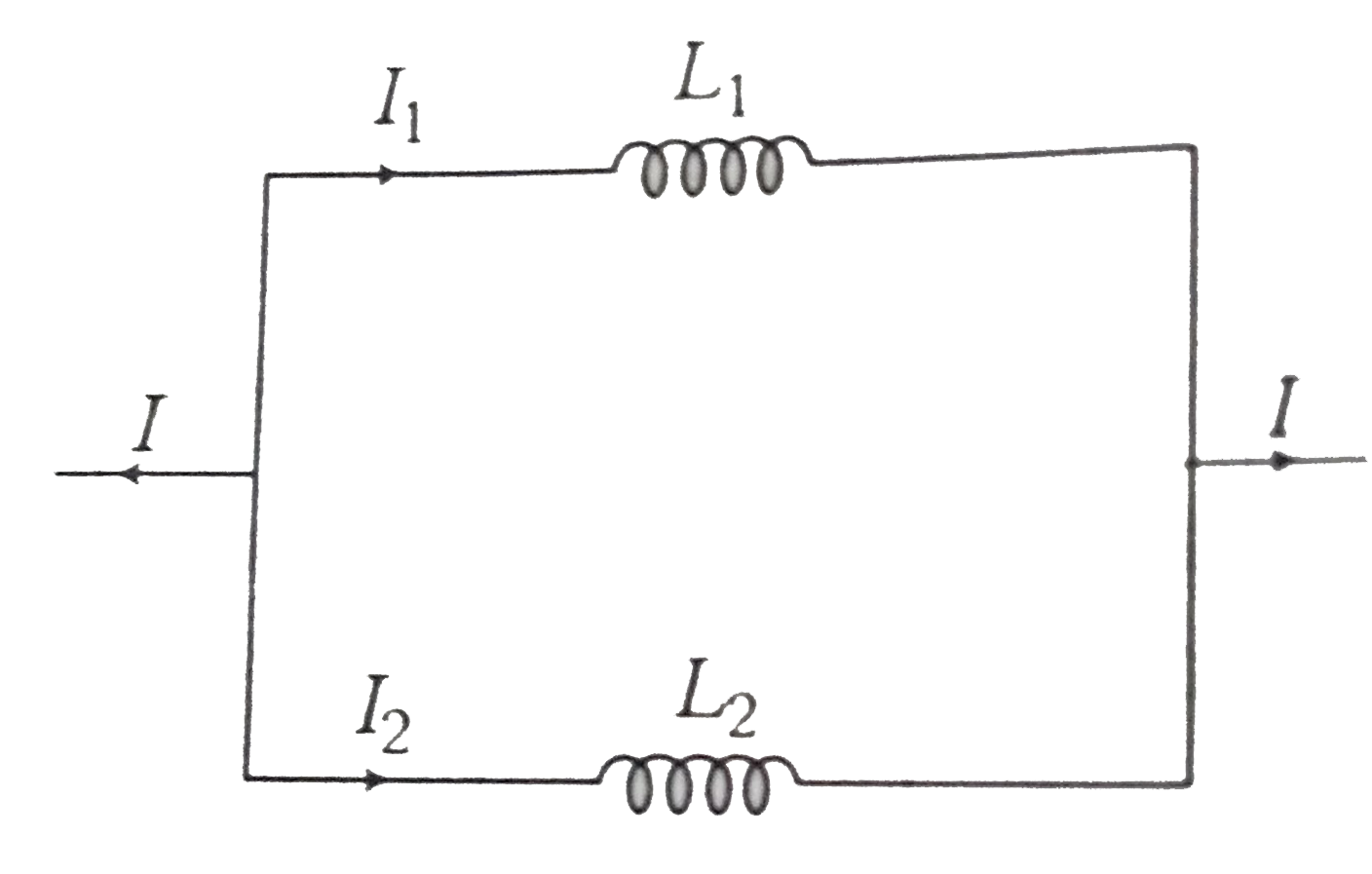
View SolutionTwo inductors L1and L2 are connected in parallel and a time varying current flows as shown in figure. Then the ratio currents l1 / l2 at any time t is
View SolutionA battery of emf epsilon and internal resistance r is connected across a load resistance RL . The plot between output power and load resistance is shown in the figure. The value of emf epsilon and internal resistance r respectively will
_PHY_E05_112_Q01.png)
View Solution

