A NOR gate and a NAND gate are connected as shown in Fig. Two different sets of inputs are given to this setup. In the first case the inputs to the gates are A=0, B=0, C=0. In the second case, the inputs are A=1, B=0, C=1, the output D in the first case and second case respectively are:

0 and 0
0 and 1
1 and 0
1 and 1
The correct Answer is:D
Let Y be the output of NOR gate and this Y is one of the input of NAND gate. Then the truth table is given by 
Similar Questions
When the inputs of a two input logic gate are 0 and 0, the output is 1. When the inputs are 1 and 0, the output is zero. The type of logic gate is
View SolutionTwo signals A, and B shown in Fig. are used as two inputs of an AND gate obtain its output wave form. Draw the logic symblo of AND gate.
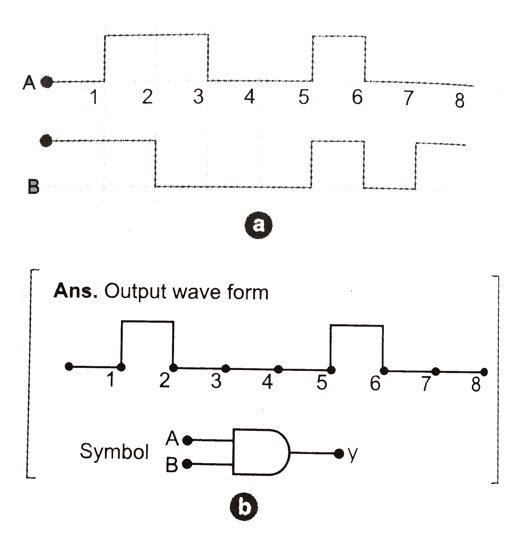
View Solution
Knowledge Check
A NOR gate and a NAND gate are connected shown. Two different sets of inputs are given to this set up. In the first case, the inputs to the gates are A = 0, B = 0, C = 0. In the second case, the inputs are A = 1, B = 0, C = 1. The output D in the first case and second case respectively are
 A0 and 0B0 and 1C1 and 0D1 and 1
When the inputs of a two input logic gate are 0 and 0, the output is 1. When the inputs are 1 and 0, the output is zero. The type of logic gate is
AXORBNANDCNORDORIn AND gate, the output Y is 1 when the inputs A and B are:
AA=1, B=0BA=1, B=1CA=0, B=0DA=0, B=1
Sketch inputs A,B and output Y from a NAND gate from the table given below
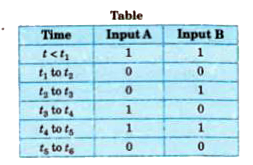
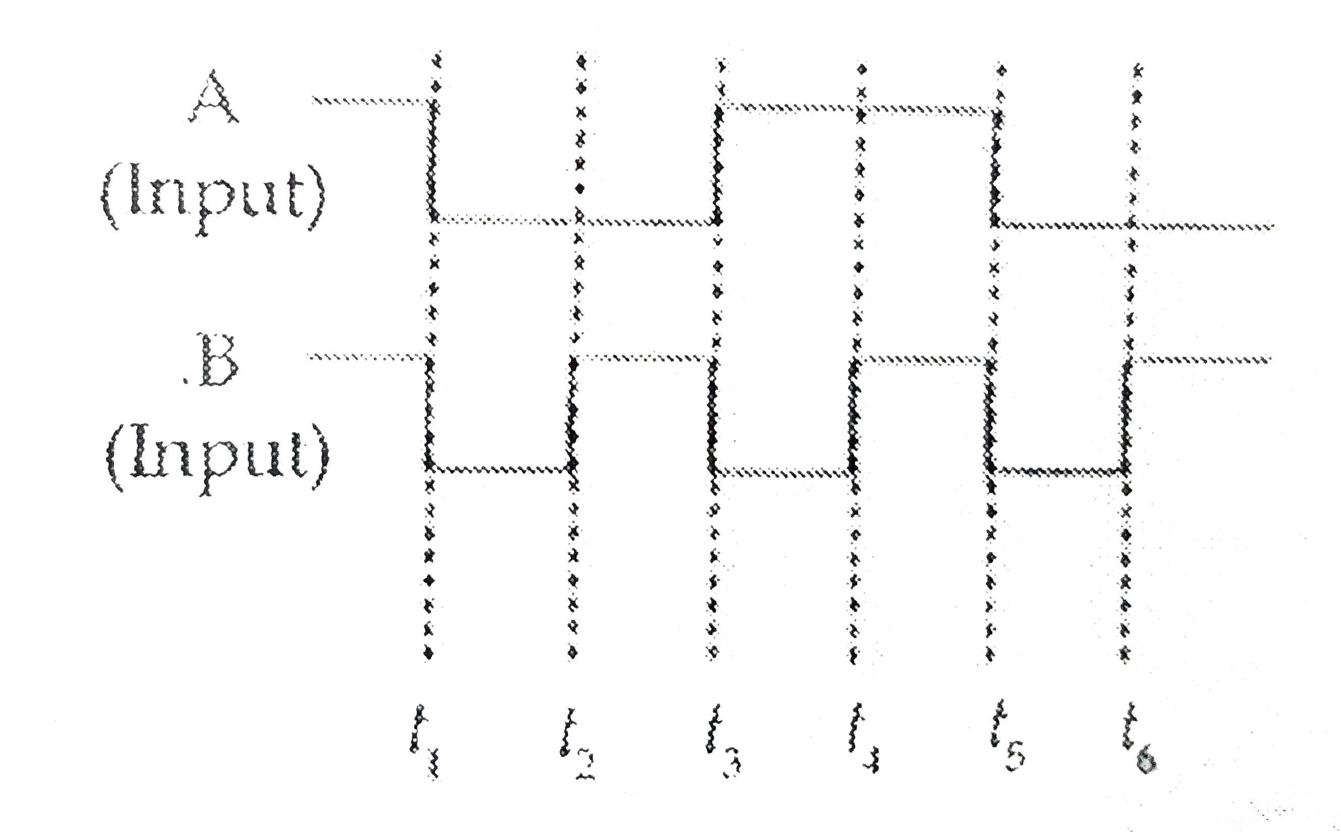
View SolutionThe given input A, B are fed to a 2-input NAND gate. Draw the output wave form of the gate
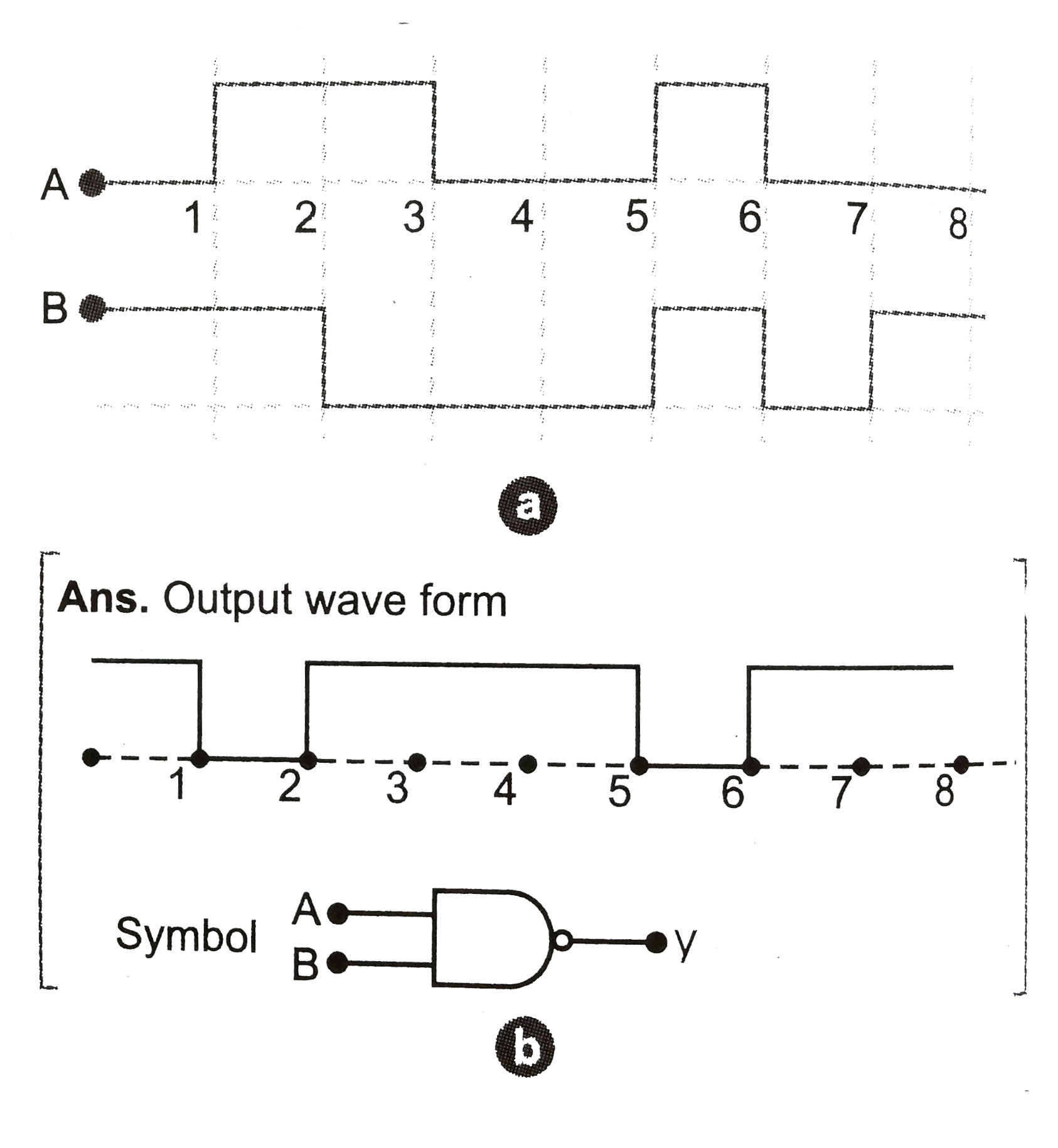
View SolutionTwo signal A and B shown in the Fig. are used as two inputs of a NAND gate. Draw its output wave form. Give the logic symbol of NAND gate.
View SolutionIn the given circuit, the binary inputs at A and B are both 1 in one case and both 0 in the next case. The respective outputs at Y in these two cases will be:
View SolutionIf A and B are two inputs in OR gate , then OR gate has an output of 0 when the value of A and B are
View Solution
