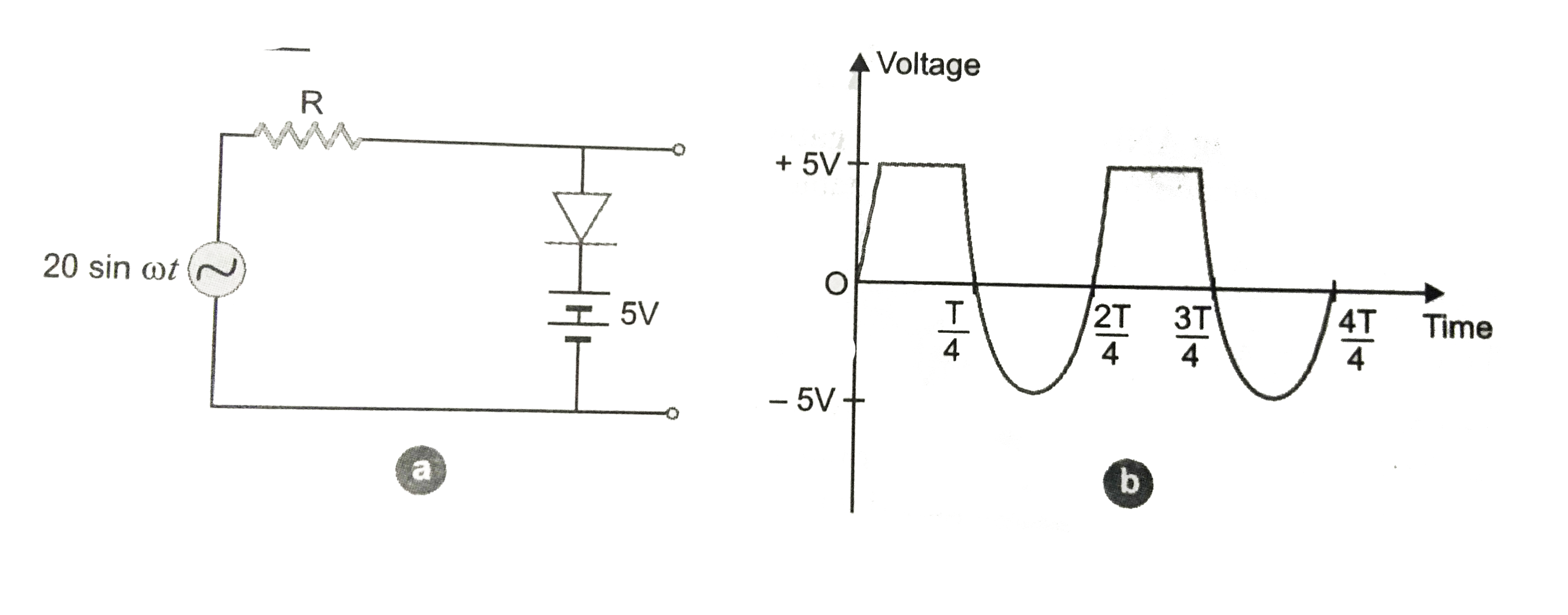
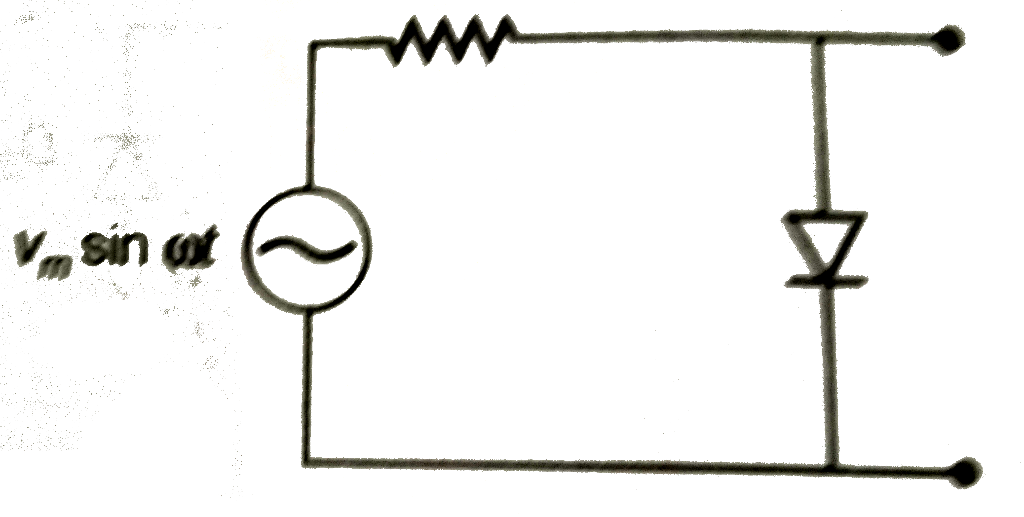
The output of the circuit given in Fig.

A
would be zero at all times
B
would be like a halfwave rectifier with positive cycles in the input
C
would be like a halfwave rectifier with negative cycles in output
D
would be like that of a full wave rectifier
Text Solution
The correct Answer is:C
The positive cycles will pass through p-n junction and only negative cycles will apear in the output.
|
Updated on:21/07/2023
Similar Questions
Knowledge Check
- Question 1 - Select One
The output of the given circuit in Fig.
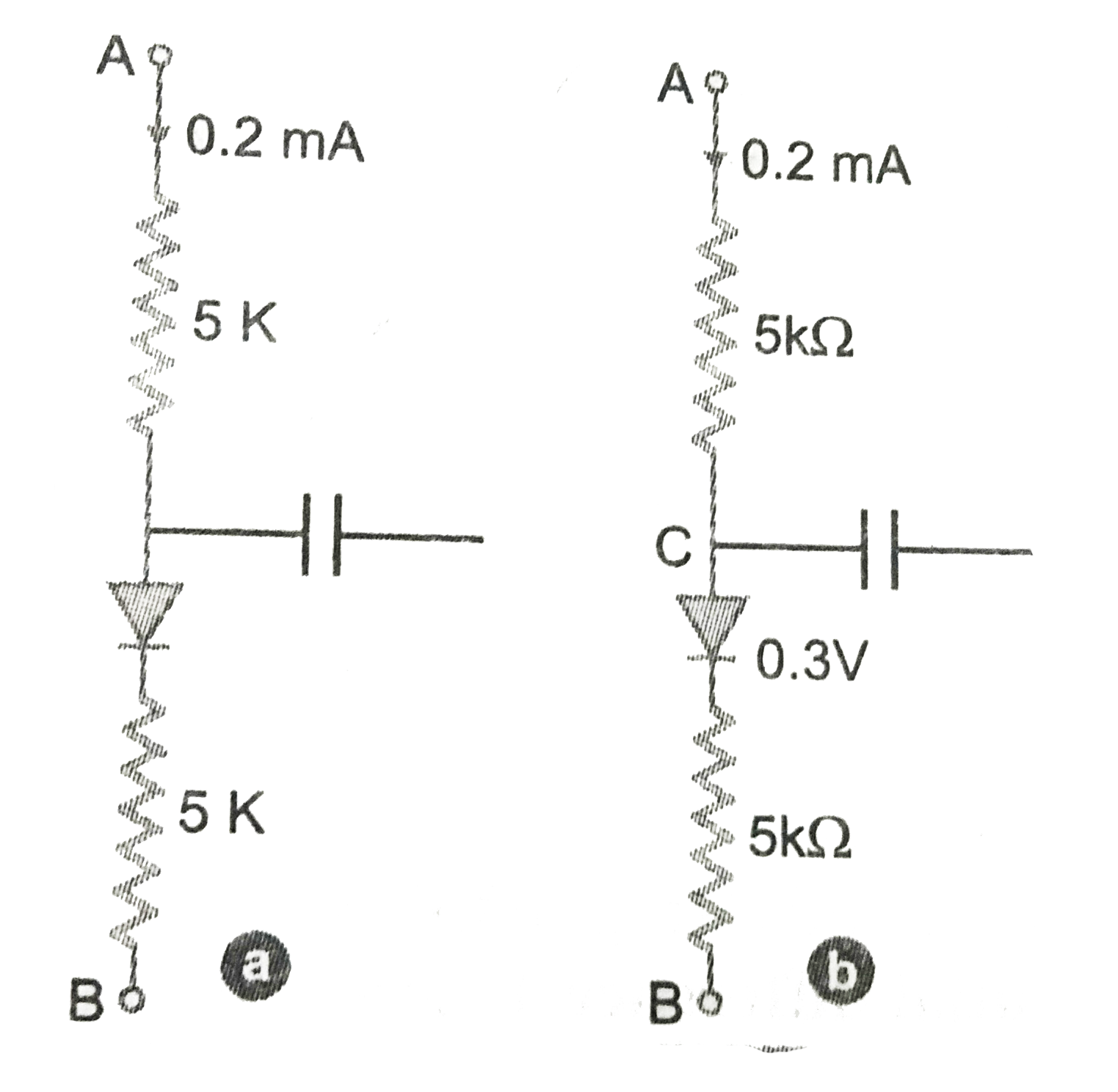 Awould be zero at all timesBwould be like a half wave rectifier with positive cycles in outputCwould be like a half wave rectifier with negative cycles in outputDwould be like that of a full wave rectifier
 - Question 2 - Select One
The output of the given circuit in Fig.
 Awould be zero at all timesBwould be like a half-wave recifier with positive cycles in outputCwould be like a half-wave rectifer with negative cycles in outputDwould be like that of a full-wave rectifier.
 - Question 3 - Select One
The output of the given circuit in Fig.
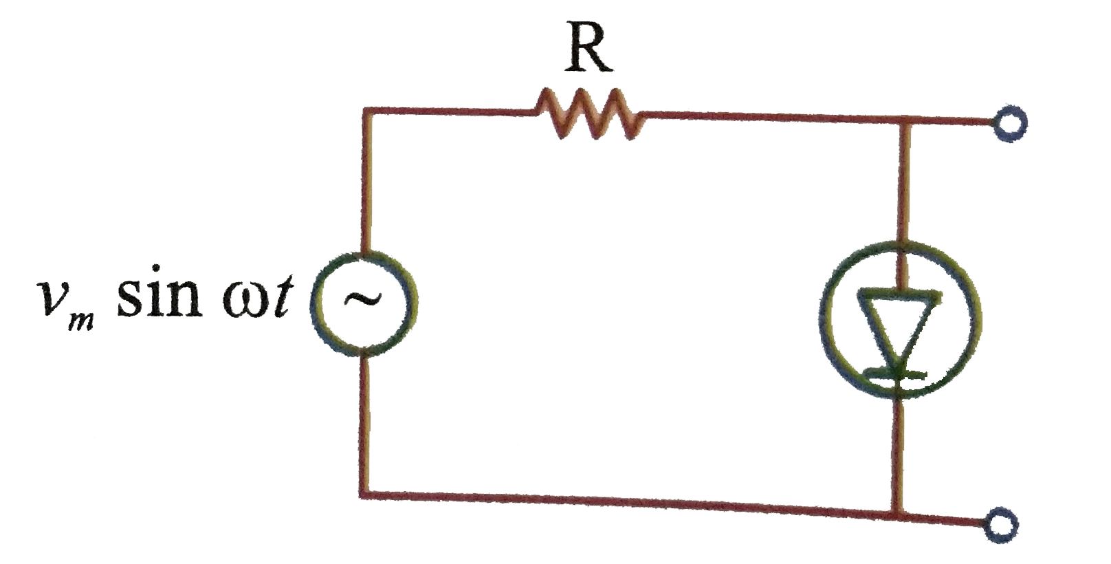 .Awould be zero at all timesBwould be like a half-wave rectifier with positive cycles in outputCwould be like a half-wave rectifier with negative cycles in outputDwould be like that of a full-wave rectifier.
The output of the given circuit in figure given below,
 View Solution
The output Y of the logic circuit given below is
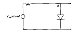
View SolutionThe output of the given circuit in Figure
 View Solution
The output of the given circuit in figure given below,
 View Solution
The output of the given circuit in figure given below,
 View Solution


