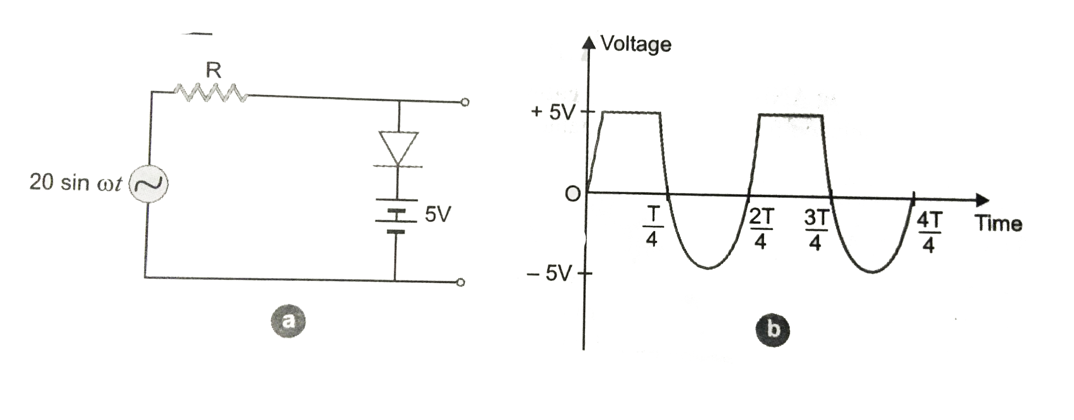
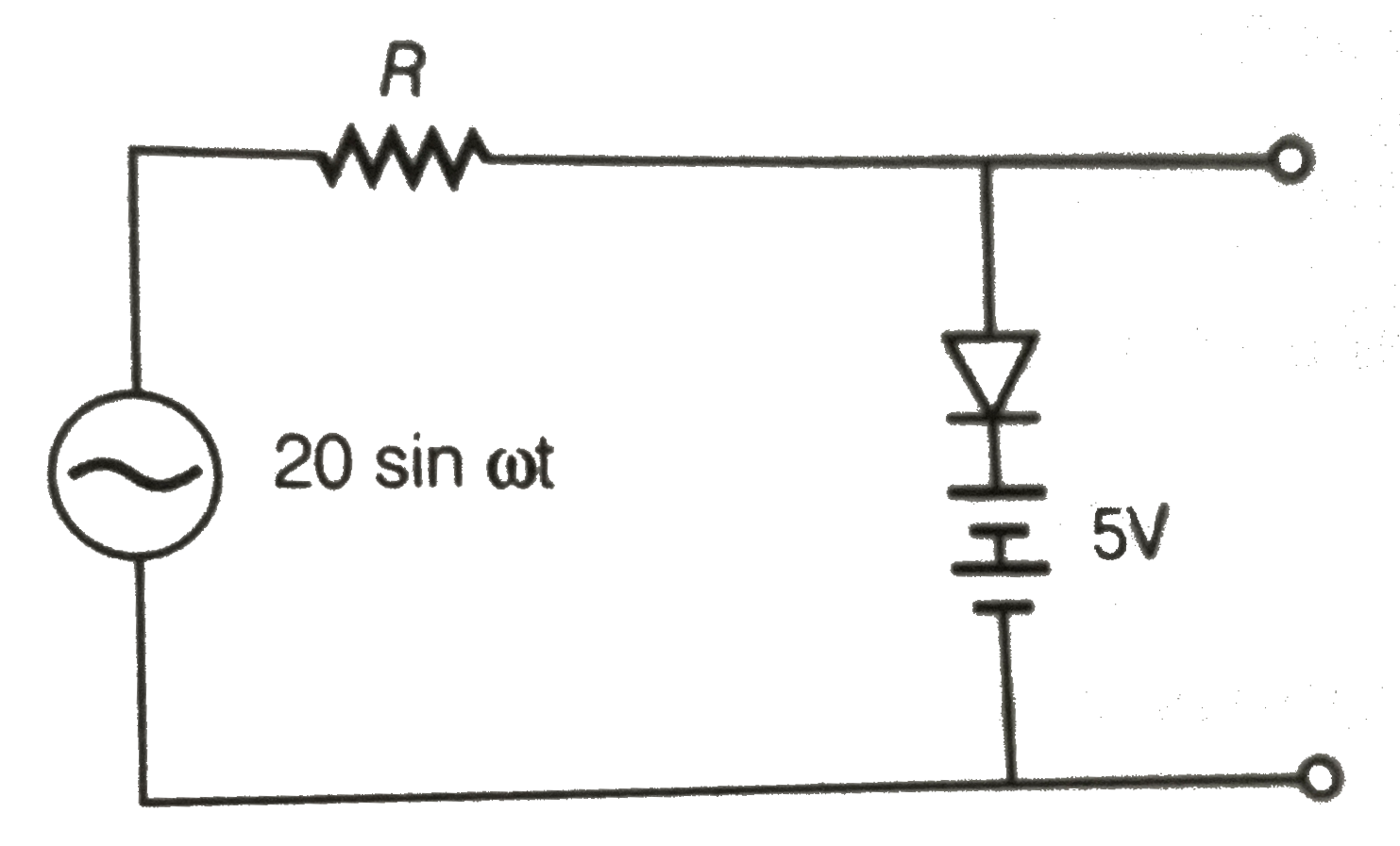
What is an ideal diode ? Draw the output waveform across the load resistor R, If the wavelength is as shown in the figure.
_S01_097_Q01.png) Solution in Gujrati
Solution in Gujrati
An ideal diode has zero resistance when forward biased and infiniter resistance when it is reversed biased. Output wave form is shown in figure.
_S01_097_S01.png)
Topper's Solved these Questions
- WAVES AND OSCILLATIONSBOOK - ALLEN CHAPTER - WAVES AND OSCILLATIONSEXERCISE - Part-1(Exercise-01)
53 Videos
- WAVES AND OSCILLATIONSBOOK - ALLEN CHAPTER - WAVES AND OSCILLATIONSEXERCISE - Part-1(Exercise-02)
19 Videos
- WAVES AND OSCILLATIONSBOOK - ALLEN CHAPTER - WAVES AND OSCILLATIONSEXERCISE - Part-2(Example)
15 Videos
- SEMICONDUCTORSBOOK - ALLEN CHAPTER - SEMICONDUCTORSEXERCISE - Part-3(Exercise-4)
50 Videos
Similar Questions
Water waves produced by a motor boat sailing in water are
View SolutionA sound wave of frequency f travels horizontally to the right. It is reflected from a large vertical plane surface moving to left with a speed v. The speed of sound in medium is C
View SolutionThe length , breadth , and thickness of a metal sheet are 4.234m,1.005m,and2.01cm, respectively. Give the area and volume of the sheet to the correct number of significant figures.
View SolutionAt absolute zero temperature Si acts as ……..
View SolutionDraw and explain the output waveform across the load resistor R, if the input wave from is as shown in Fig.

View SolutionDraw the output waveform across the resistor (Fig.)
View SolutionAssuming the ideal diode, draw the output waveform for the circuit given in Fig.Explain the waveform.

View SolutionAn ideal diode is connected in a circuit with resistance R=5Omega and V=10 volt as shown in figure maximum and minimum value of output voltage. When no load applied is (assume diode to be ideal)
View SolutionA square wave (-1 to +1V) is applied to a P-N junction diode as shown. Draw the output wave form across the diode which is assumed to be ideal-
View SolutionA d.c. battery of V volt is connected to a series combination of a resistor R and an ideal diode D as shown in the figure below. The potential difference across R will be
View SolutionAssuming the ideal diode, draw the output waveform for the circuit given in fig. (a), explain the waveform

View SolutionFour silicon diodes are connected as shown in the figure. Assuming the diodes to be ideal. The current through the resistor R is
View SolutionDraw and explain the output waveform across the load resistor R, if the input waveform is as shown in the given.
View SolutionDraw the output waveform across the resistor.
View SolutionAssuming the ideal diode, draw the output waveform for the circuit given in figure. Explain the waveform.
View SolutionDraw the output waveform across the resistor (Fig.)
View Solution
