Bharat takes five identical bulbs B1,B2,B3,B4 and B5 and connects them to a cell as shown in the figure. He compares
(i) The current passing through the different bulbs and
(ii) the potential difference across different bulbs when the circuit is closed. What does he conclude?
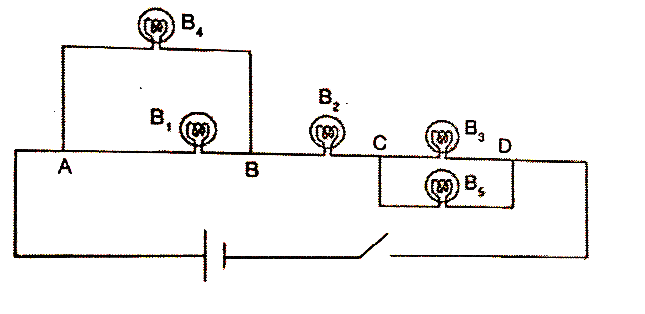
When the circuit is closed, current starts flowing from the positive electrode of the cell. At .A. the total current splits, a part passes through .B1. and other part passes through .B4.. As all the bulbs are identical, the resistance offered by them is the same. If the total current flowing in the circuit is i, at A it splits into two equal halves, and a current of .i/2. passes through B1andB4. Here, B1 and B4 are connected in parallel between A and B. As B2 is connected in series the current that passes through it is .i.. Similarly, B3 and B5 are connected in parallel between C and D. Hence, .i/2. current passes through both of them. Their potential difference depends on the current that passes through the different bulbs. As shown, the potential drop across B1,B4,B3andB5 is equal and the potential drop across B, is twice that of the others.
Topper's Solved these Questions
- ELECTRICITYBOOK - PEARSON IIT JEE FOUNDATIONCHAPTER - ELECTRICITYEXERCISE - CONCEPT APPLICATION (Level 2)
19 Videos
- DYNAMICSBOOK - PEARSON IIT JEE FOUNDATIONCHAPTER - DYNAMICSEXERCISE - CONCEPT APPLICATION(LEVEL 3)
15 Videos
- ELECTROMAGNETISMBOOK - PEARSON IIT JEE FOUNDATIONCHAPTER - ELECTROMAGNETISMEXERCISE - CONCEPT APPLICATION ( LEVEL 2)
20 Videos
Similar Questions
Bharat takes five identical bulbs B1,B2,B3,B4 and B5 and connects them to a cell as shown in the figure. He compares
(i) The current passing through the different bulbs and
(ii) the potential difference across different bulbs when the circuit is closed. What does he conclude?

View SolutionIn the circuit shown in the figure , no current flows through the 8 Ω resistor, then the potential difference between points A and B(VA−VB)is
_PHY_E01_001_Q01.png)
View Solution
Knowledge Check
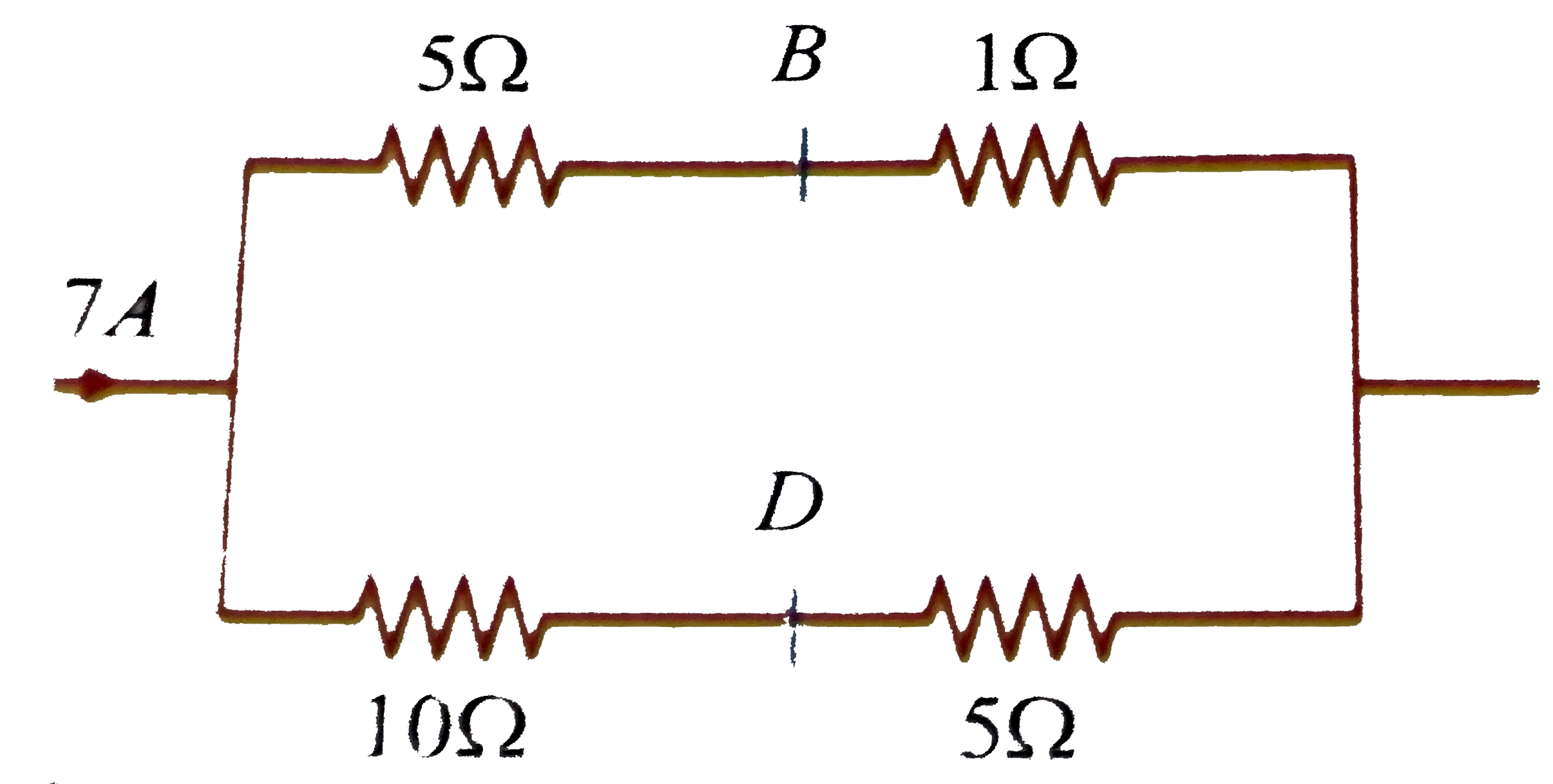
A current of 7 A flows through the circuit as shown in the figure the potential difference across points B and D isA5VB3VC10VD7VIn the shown circuit, what is the potential difference across A and B
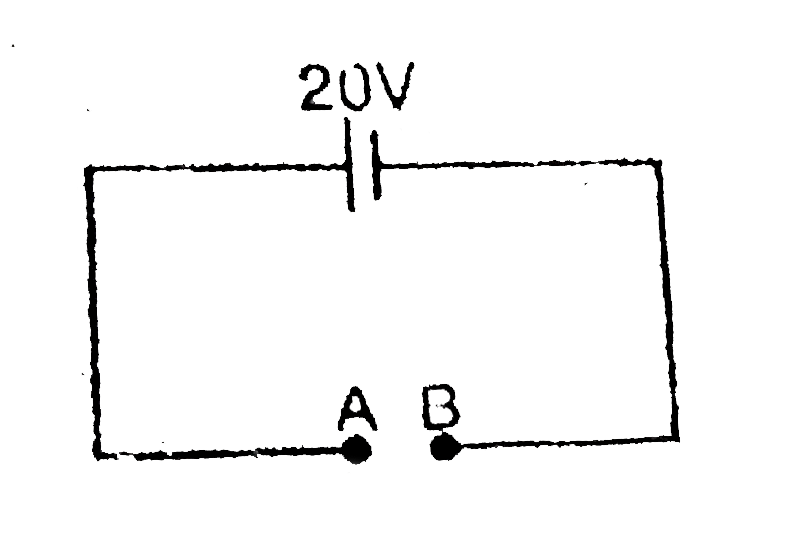 A50 VB45 VC30 VD20 V
The potential difference between points A and B in the circuit shown in figure will be
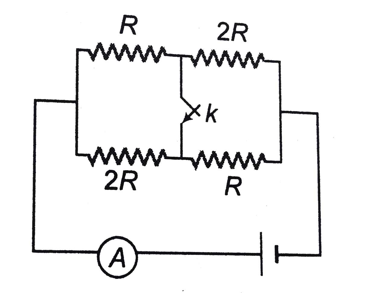 A1VB2VC−3VDnone of these
In the given circuit, calculate -
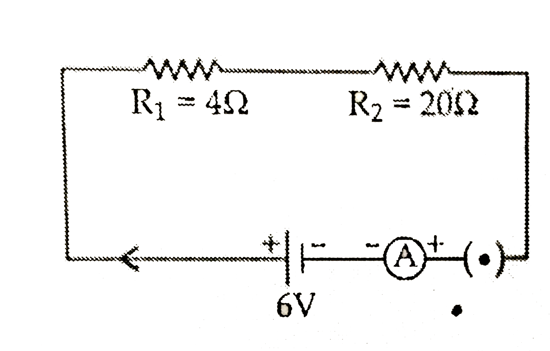
(a) the total resistance of the circuit,
(b) the current through the circuit, and
(c) the potential differences across R1andR2
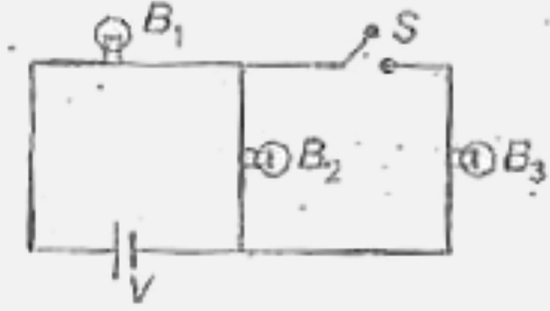
View SolutionThree identical bulbs B1,B2 and B3 are connected to the mains as shown in figure. If B3 is disconnected for the from the circuit by opening switch S, then incandescence of bulb B1 will . ,
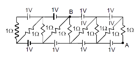
View SolutionFind the potential difference VA−CB for the circuit shown in the figure .
View SolutionWhat is the power rating (in W) of a bulb if a current of 0.3 A passes through on application of 240 V of potential difference across its terminals?
View SolutionWhat is the power rating (in W) of a bulb if a current of 0.1A passes through on application of 250V of potential difference across its terminals?
View Solution
