Draw in your notebook the symbols to represent the following components of electrical circuits: connecting wires, switch in the 'OFF' position, bulb, cell, switch in the 'ON' position, and battery.
To draw the symbols representing various components of electrical circuits, follow these steps:
1. Connecting Wires:
- Draw a straight line to represent connecting wires. This line indicates the path through which the electric current flows.
2. Switch in the 'OFF' Position:
- Draw a break in a line (representing the wire) with a small circle at one end. This indicates that the circuit is open and the switch is in the 'OFF' position.
3. Bulb:
- Draw a circle with a small filament inside (a zigzag line) to represent a bulb. This symbolizes the light-emitting component of the circuit.
4. Cell:
- Draw a long rectangle with a shorter rectangle on top. This represents a single cell, which is a source of electrical energy.
5. Switch in the 'ON' Position:
- Draw a line connecting two ends of the wire with a small circle in the middle. This indicates that the circuit is closed and the switch is in the 'ON' position.
6. Battery:
- Draw multiple cells (rectangles with shorter rectangles on top) connected together. This represents a battery, which is made up of several cells providing a combined voltage.
Final Representation:
- Connecting Wires: ─
- Switch in the 'OFF' Position: ⊗ (with a break in the line)
- Bulb: ⊙ (with a zigzag line inside)
- Cell: ┌───┐
- Switch in the 'ON' Position: ⊕ (with a line connecting both ends)
- Battery: ┌───┐ ┌───┐ (multiple cells connected)
- Draw a straight line to represent connecting wires. This line indicates the path through which the electric current flows.
- Draw a break in a line (representing the wire) with a small circle at one end. This indicates that the circuit is open and the switch is in the 'OFF' position.
- Draw a circle with a small filament inside (a zigzag line) to represent a bulb. This symbolizes the light-emitting component of the circuit.
- Draw a long rectangle with a shorter rectangle on top. This represents a single cell, which is a source of electrical energy.
- Draw a line connecting two ends of the wire with a small circle in the middle. This indicates that the circuit is closed and the switch is in the 'ON' position.
- Draw multiple cells (rectangles with shorter rectangles on top) connected together. This represents a battery, which is made up of several cells providing a combined voltage.
- Switch in the 'OFF' Position: ⊗ (with a break in the line)
- Bulb: ⊙ (with a zigzag line inside)
- Cell: ┌───┐
- Switch in the 'ON' Position: ⊕ (with a line connecting both ends)
- Battery: ┌───┐ ┌───┐ (multiple cells connected)
Topper's Solved these Questions
- ELECTRIC CURRENT AND ITS EFFECTS BOOK - NCERTCHAPTER - ELECTRIC CURRENT AND ITS EFFECTS EXERCISE - Exercise (Fill in the blanks)
4 Videos
- ELECTRIC CURRENT AND ITS EFFECTS BOOK - NCERTCHAPTER - ELECTRIC CURRENT AND ITS EFFECTS EXERCISE - Exercise (True .T. and False .F.)
4 Videos
- HEAT BOOK - NCERTCHAPTER - HEAT EXERCISE - Exercise
16 Videos
Similar Questions
Knowledge Check
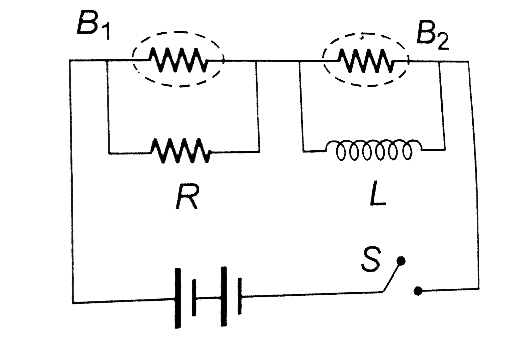
If the switch in the following circuit is turned off, then
 Athe bulb B1 will go out immediately whereas B2 after sometimesBthe bulb B2 will go out immediately whereas B1 after sometimesCboth B1 and B2 will go immediatelyDboth B1 and B2 will go out after sometimes
Draw the symbols of the following circuit components.
battery
View SolutionDraw the symbols of commonly used components in electrical circuit diagrams.
View SolutionDraw the symbols of the following circuit components.
switch in off position
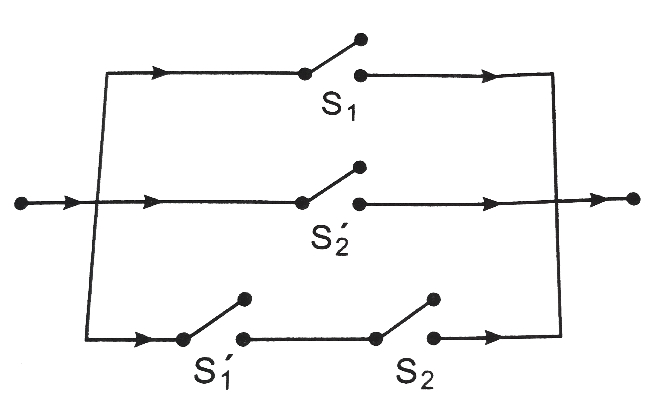
View SolutionFind the symbolic form of the following switching circuit, construct its switching table and interpret it.

View SolutionIn which of the following circuits can the electrical bulb be operated using the switch in the circuit?
View SolutionDraw a circuit diagram which includes the following :
A cell, a bulb, a closed switch.
View SolutionArrange the following components in a circuit diagram such that the bulb glows. (a) Cell 1 (b) Cell B (c) Bulb (d) Switch

View Solution
