Give the principle, construction and working of an a.c. generator.Solution in Punjabi
An electric generator : It is an electrical device which is used to convert mechanical energy into electrical energy.
But the word generator is a misnomer. Generator generates nothing but only converts one form of energy into another.
Principle : Its working is based upon the principle of mutual induction i.e.,
..An induced emf is produced in a coil whenever there is change in magnetic flux in the neighbouring coils.
Construction : It consists of following parts :
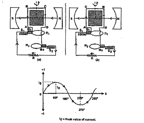
(i) Armature : Armature coil (ABCD) consists of large number of turns of insulated copper wire wound over a soft iron core. It can rotate about central axis.
(ii) Field magnet : The field magnet NS is an electromagnetic or permanent magnet in the field of which the armature rotates.
(iii) Slip rings : The two ends of coil are connected to two slip rings R1 and R2. These rings rotate along with the armature coil.
(iv) Brushes : There are two carbon brushes B1 and B2 which are kept fixed and touch R1 and R2 lightly. These are used to pass the current from armature coil to external load R.
Working : As the armature coil is rotated in the magnetic field, angle θ between the field and normal to coil changes continuously. So magnetic flux linked with the coil changes. An emf is induced in the coil.
Suppose the plane of coil is perpendicular to plane of paper in which magnetic field is applied with AB at front and CD at the back. The amount of magnetic flux linked with the coil in this position is maximum. As the coil is rotated anticlockwise, AB moves inwards and CD moves outwards. The amount of magnetic flux linked with the coil changes. According to Fleming.s right hand rule, current induced in AB is from A to B and in CD, it is from C to D. In the external circuit, current flows from B2 to B1, as shown in Fig. (a).
After half rotation of coil, AB is at back and CD is at front. Therefore, on rotation further, AB moves outwards and CD moves inwards. The current induced in AB is from B to A and in CD, it is from D to C. Through external circuit, current flows from B1 to B2 as shown in Fig. (b). When the coil is rotated continuously, the above process is repeated and induced current in the external circuit changes direction after every half rotation of the coil. Hence, the current induced in the coil external circuit will be alternating in nature as shown in Fig.

Suppose
n= Number of turns in the coil.
A= Face area enclosed by each turn of the coil.
→B= Strength of magnetic field.
ω= Uniform angular velocity of coil in clockwise direction.
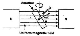
Starting from vertical position, let the armature be in the position shown in fig. any instant t. Normal to armature at this instant makes an angle ωt with →B. The magnetic flux ϕB(t) at any instant t through each turn of the armature is given by the dot product of the face area →A and the magetic field →B, i.e.,
ϕB=n→B.→A=nBAcosθ=nBAcosωt
As the coil is rotated, magnetic flux linked with the coil changes and hence an e.m.f. is induced in the coil. At this instant t, if E is the e.m.f. induced in the coil, then
E=dϕBdt=−ddt(nBAcosωt)
=−nBAddt(cosωt)
=−nBA(−sinωt)ω
E=nBAωsinωt
The induced e.m.f. will be maximum, when
sin ωt = maximum = 1
Emax=E0=nBAω×1
Therefore, eqn. (2) becomes E=E0sinωt

Topper's Solved these Questions
- ELECTRICAL DEVICESBOOK - BETTER CHOICE PUBLICATIONCHAPTER - ELECTRICAL DEVICESEXERCISE - NUMERICAL PROBLEMS
3 Videos
- ELECTRICAL DEVICESBOOK - BETTER CHOICE PUBLICATIONCHAPTER - ELECTRICAL DEVICESEXERCISE - (MOST EXPECTED QUESTIONS 1 MARKS)
7 Videos
- ELECTRICAL DEVICESBOOK - BETTER CHOICE PUBLICATIONCHAPTER - ELECTRICAL DEVICESEXERCISE - SHORT ANSWERS TYPE QUESTIONS (3/4 MARKS)
5 Videos
- ELECTRIC FIELDBOOK - BETTER CHOICE PUBLICATIONCHAPTER - ELECTRIC FIELDEXERCISE - NUMERICAL PROBLEMS (MOST EXPECTED QUESTIONS)
4 Videos
- ELECTRICAL MEASUREMENTSBOOK - BETTER CHOICE PUBLICATIONCHAPTER - ELECTRICAL MEASUREMENTSEXERCISE - Most Expected Questions
7 Videos
Similar Questions
An electric motor operating on 50 V.D.C supply draws a current of 12 ampere. If the efficiency of motor is 30%, estimate the resistance of the motor.
View SolutionState the factors on which induced e.m.f. in a coil rotating in a uniform magnetic field depends.
View SolutionExplain principle and theory of Transformer with the help of diagram.
View SolutionA charged plastic spherical ball of mass 8.4×10⁻¹⁴kg is found to remain suspended in a uniform electric field of Entensity 5×10²NC−1. Calculate the charge on the ball.
View SolutionWhy is a slide wire bridge also called a metre bridge?
View SolutionDescribe the principle, construction and working of an AC generator.
View SolutionDescribe the principle, construction and working of a DC generator.
View SolutionExplain with a labelled diagram, the principle, construction and working of an electric generator.
View SolutionOn what principle is an a.c. generator based ?
View SolutionDraw a neat labelled diagram of an ac generator or dynamo.
View SolutionDescribe the principle, construction and working of an AC generator.
View SolutionGive the principle, construction and labelled diagram of AC generator.
View SolutionState the working principle of A.C. generator.
View SolutionState the principle of A.C generator
View SolutionState principle of an a.c. generator.
View Solution
