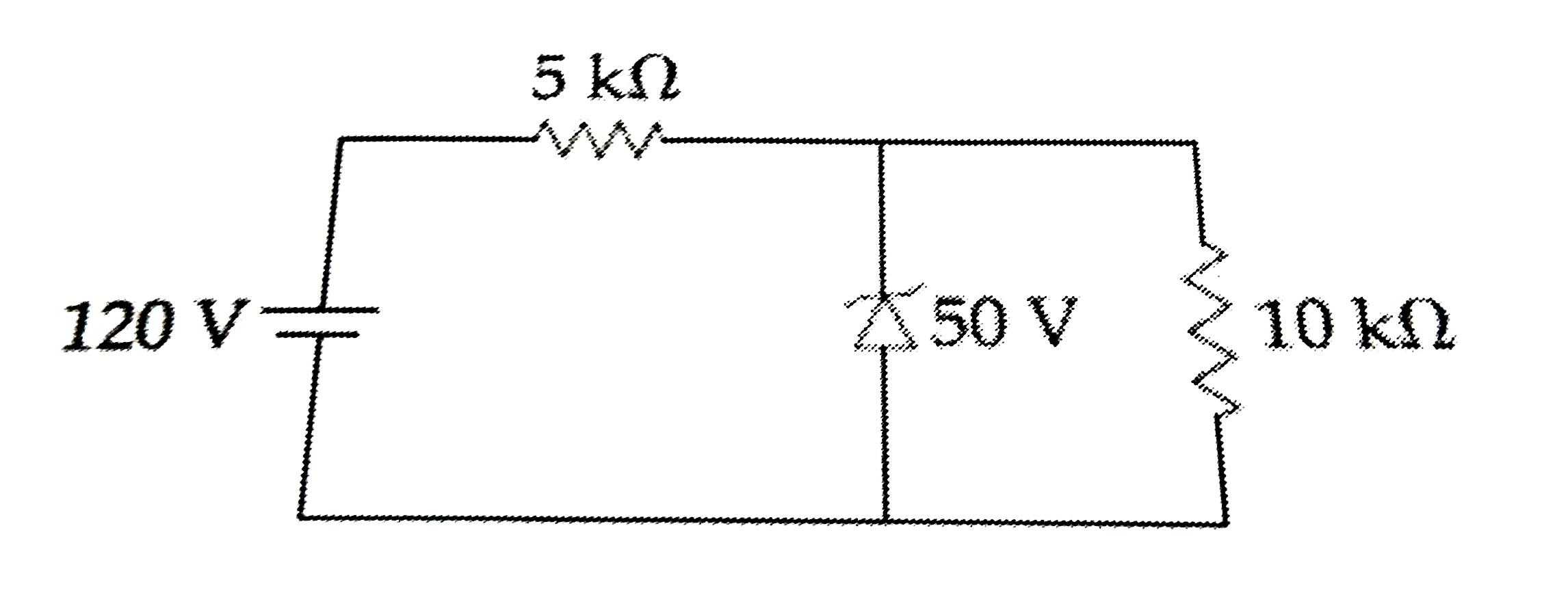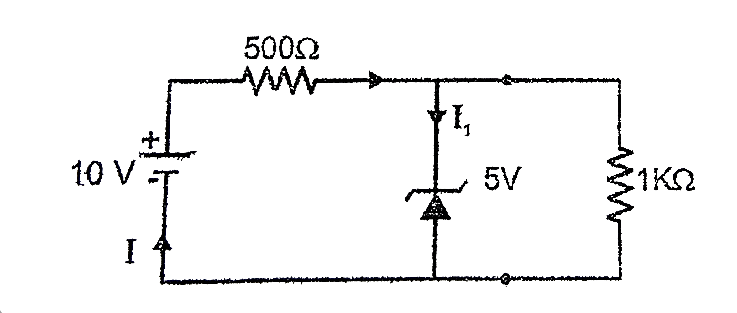
The current flowing through the zener diode in fig is-
A
20 mA
B
25 mA
C
15 mA
D
5 mA
Video Solution
Text Solution
The correct Answer is:D
IL=5V1kΩ=5mA
I=10−5500=10mA
I1=I−IL=10mA−5mA=5mA
_E01_390_S01.png)
|
Updated on:21/07/2023
Topper's Solved these Questions
- BOOK - ALLENCHAPTER - SEMICONDUCTORSEXERCISE - Part-3(Exercise-3)27videos
SEMICONDUCTORS
- BOOK - ALLENCHAPTER - SEMICONDUCTORSEXERCISE - Part-3(Exercise-4)51videos
SEMICONDUCTORS
- BOOK - ALLENCHAPTER - SEMICONDUCTORSEXERCISE - Part-3(Exercise-1)84videos
SEMICONDUCTORS
- BOOK - ALLENCHAPTER - PHYSICAL WORLD, UNITS AND DIMENSIONS & ERRORS IN MEASUREMENT EXERCISE - EXERCISE-IV8videos
PHYSICAL WORLD, UNITS AND DIMENSIONS & ERRORS IN MEASUREMENT
- BOOK - ALLENCHAPTER - WAVES AND OSCILLATIONSEXERCISE - Part-1(Exercise-05)[B]42videos
WAVES AND OSCILLATIONS
Similar Questions
Knowledge Check
- Question 1 - Select One
In the circuit, Fig The current through the zener diode is
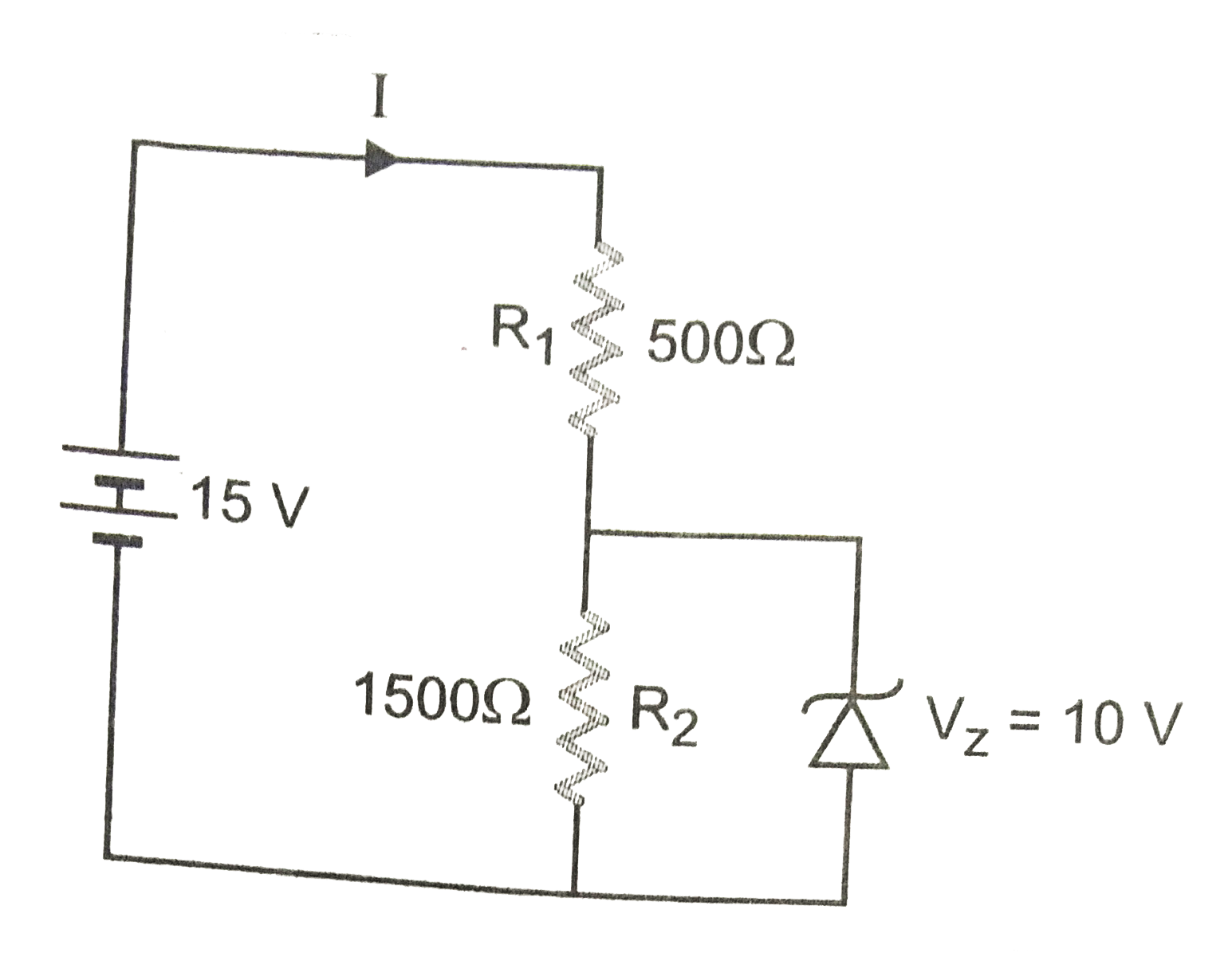 A10 mAB6.67 mAC5 mAD3.33 mA
 - Question 2 - Select One
From the Zener diode circuit shown in figure, the current through the Zener diode is
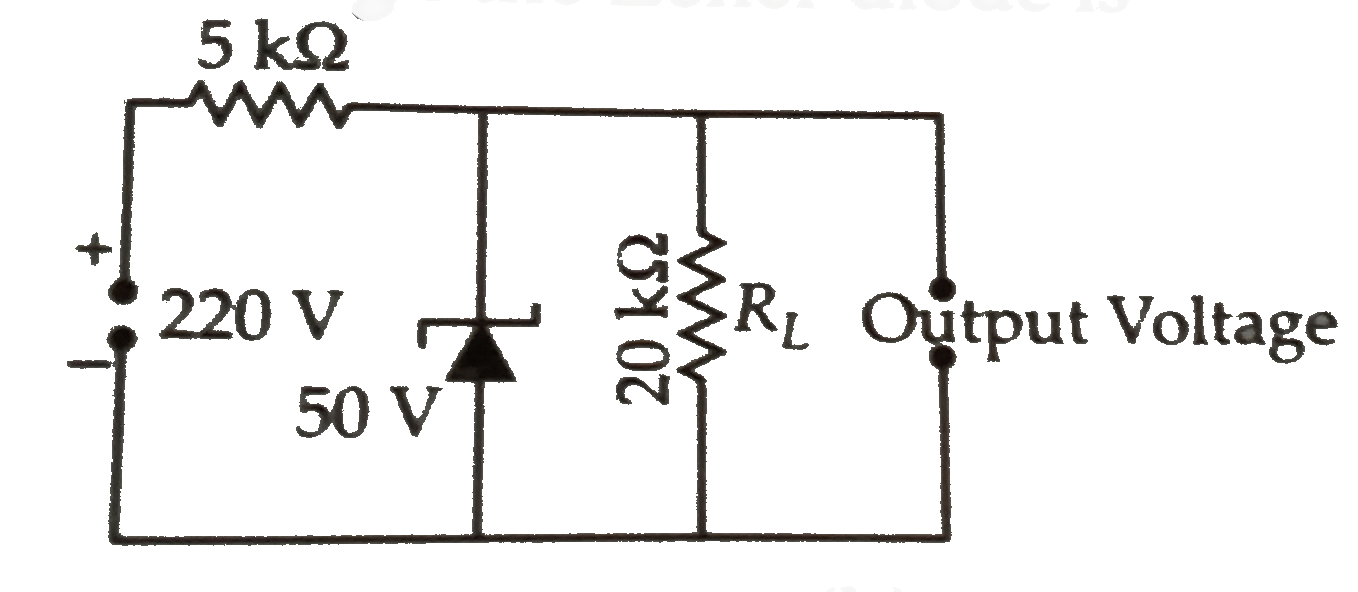 A34 mAB31.5 mAC36.5 mAD2.5 mA
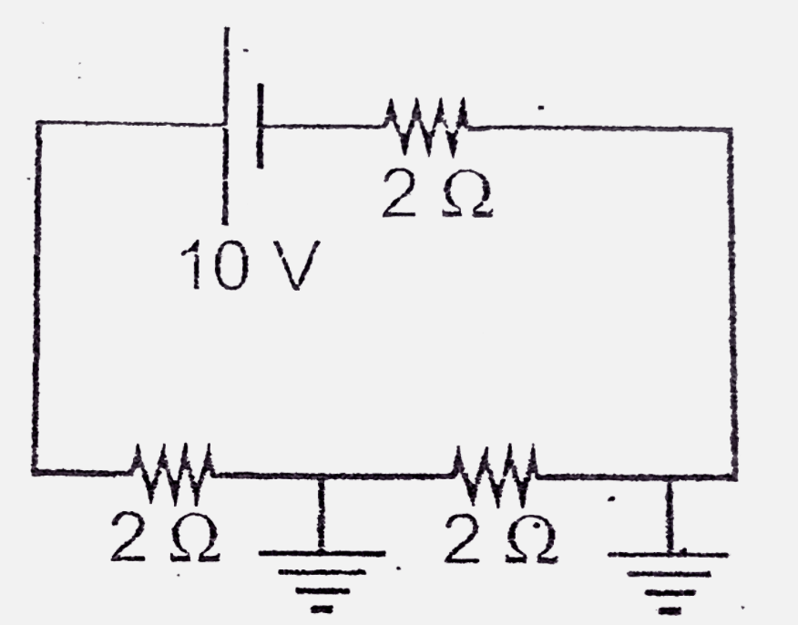
The current flowing through the cell in the circuit shown is
 View Solution
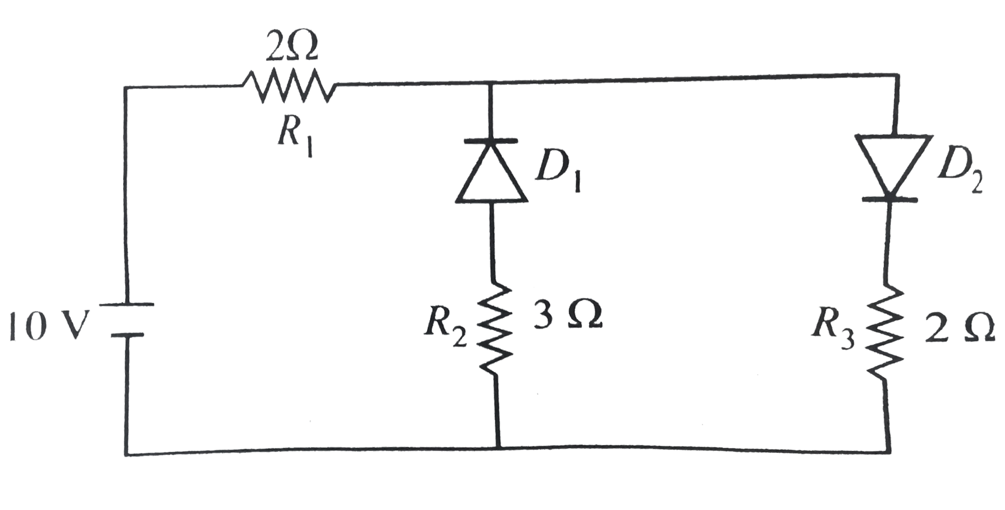
The given circuit has two ideal diodes connected as show in the figure. The current flowing through the resistance R1 will be
 View Solution
The given circuit has two ideal diodes connected as shown in the figure below. The current flowing through the resistance R1 will be
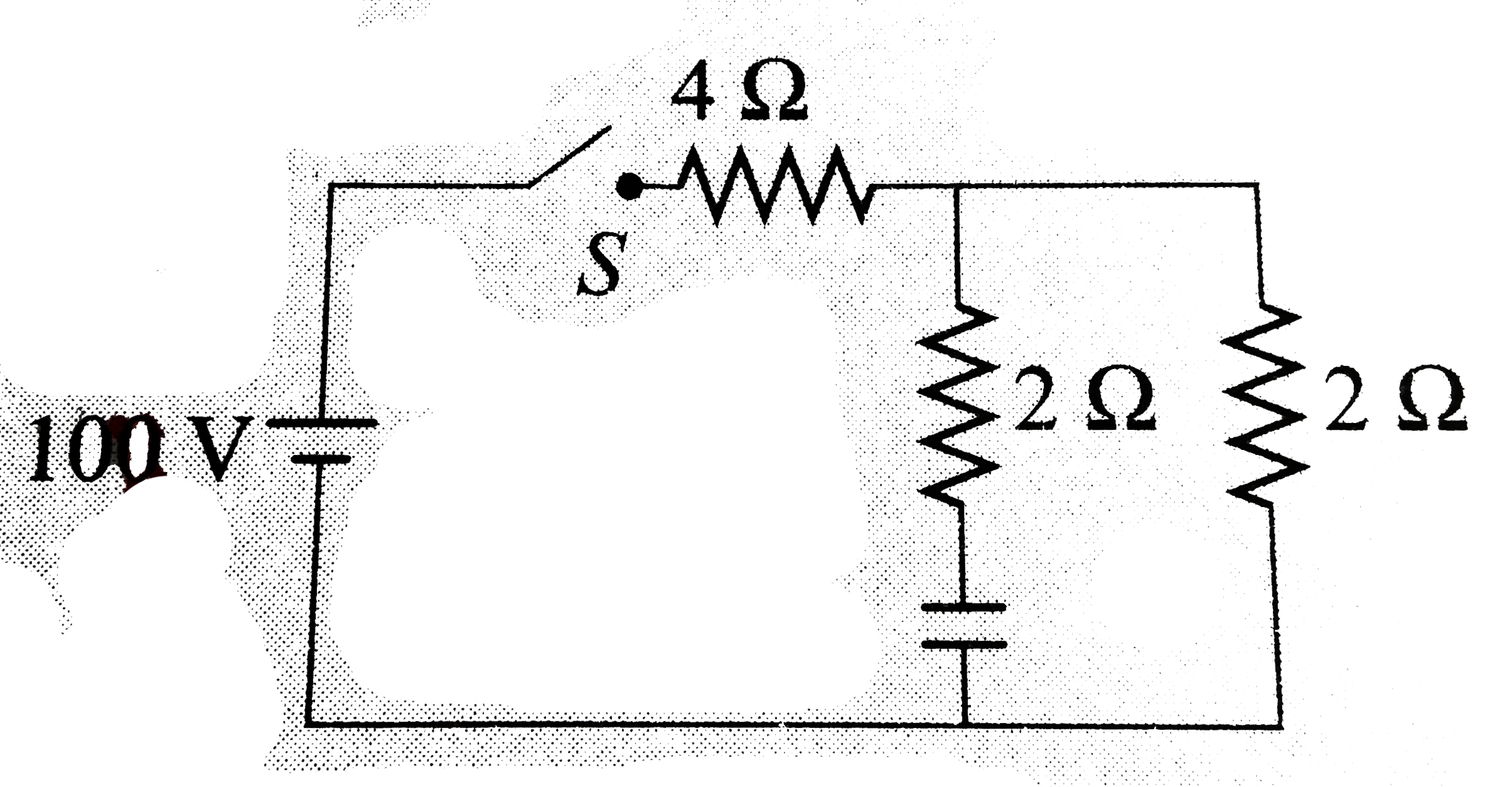
View SolutionCalculate the current flowing through the capacitor branch in the circuit shown in Fig. 5.187, initially and finally,
 View Solution
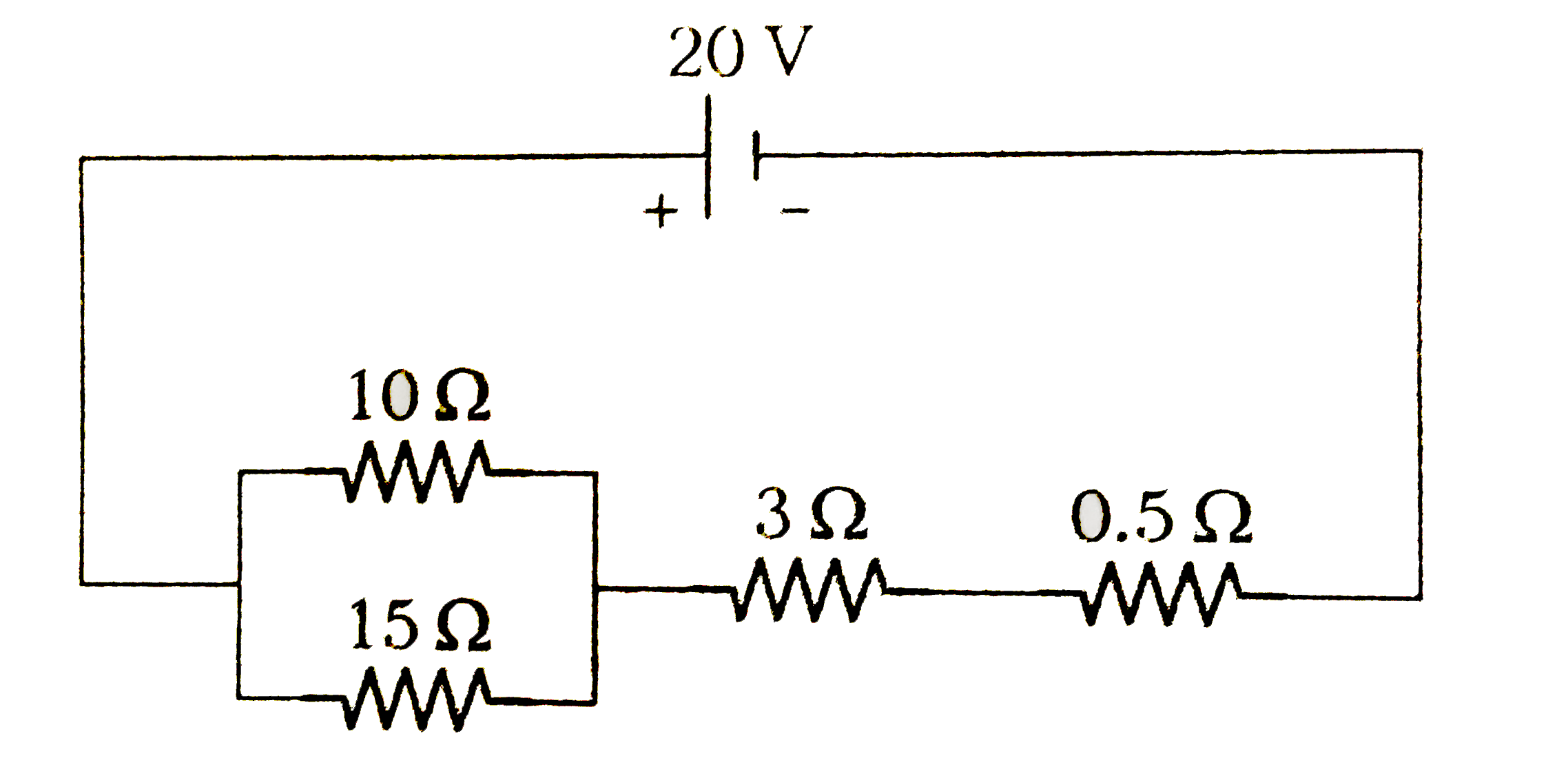
In the circuit, the current flowing through 10Ω resistance is
 View Solution
Zener diode is used as
View Solution


