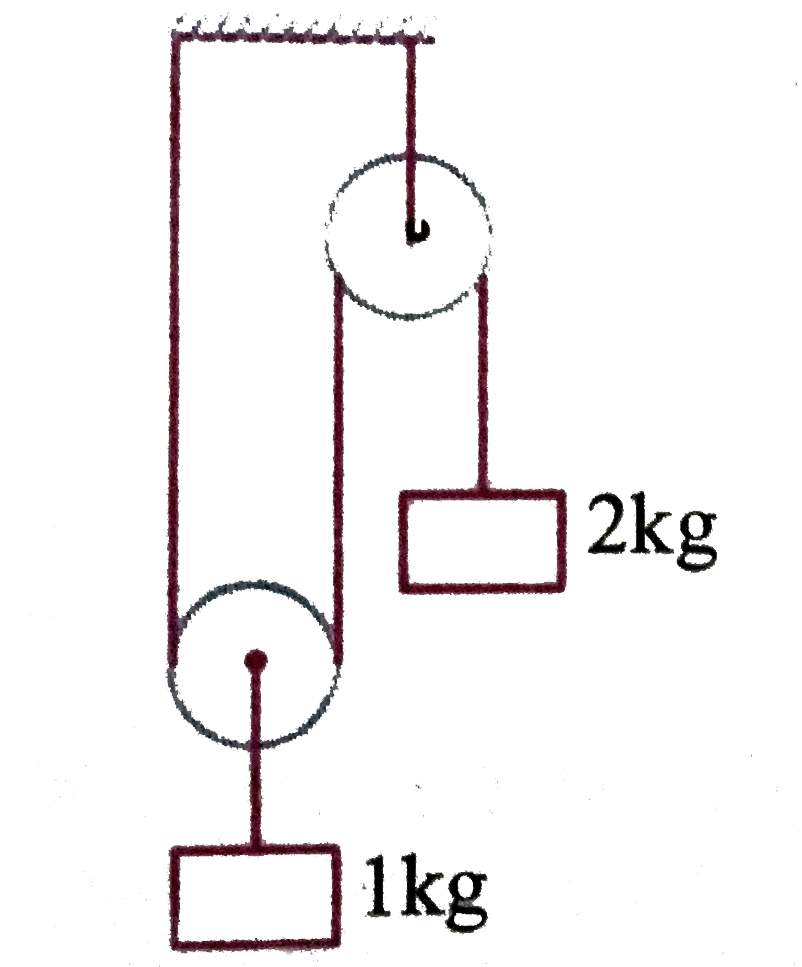
In the balance machine shown in the figures. Which arm will move downward after the system is released from rest (assuming stiring, arm of balance machie and the pulley to be light)
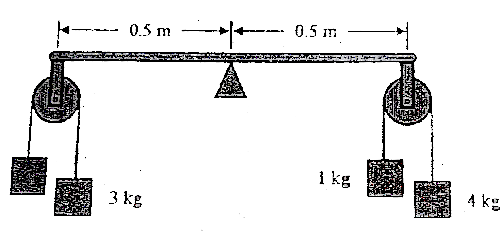
Left
Right
remains stationary
None of these
The correct Answer is:A
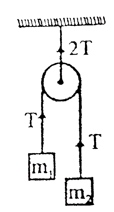
Where T=2m1m2m1+m2g
Here τ=T1l−T2l
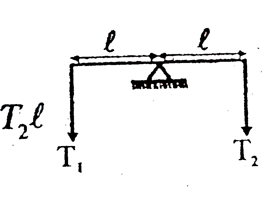
and ∵T1>T2
T1=2×2×32+3×10=24N
T2=2×4×14+1×10=16N
Topper's Solved these Questions
Similar Questions
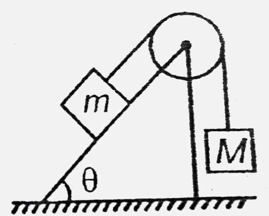
Wedge shown in the figure is fixed . System is released from rest (Neglect friction )
 View Solution
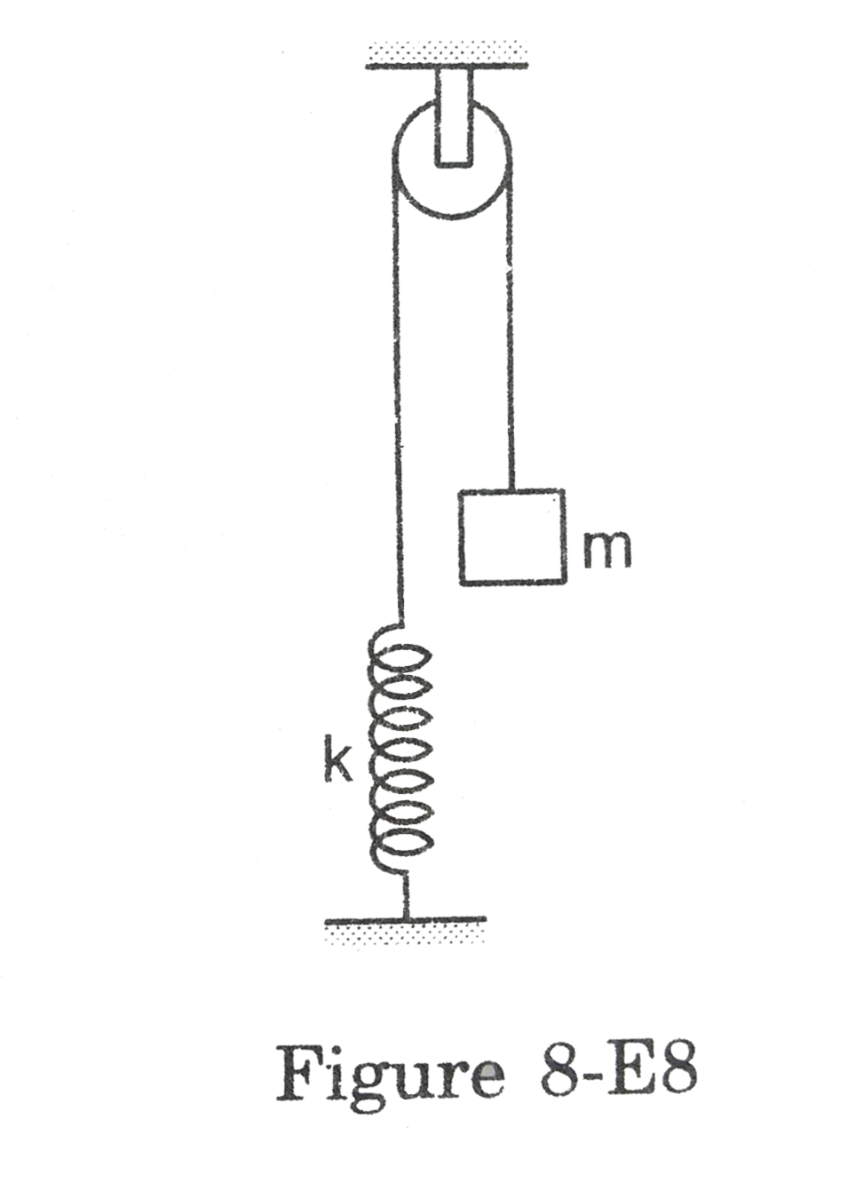
Consider the situation shown in figure. Initially the spring is unstretched when the system is released from rest. Assuming no friction in the puley, find the maximum eleongation of the spring.
 View Solution
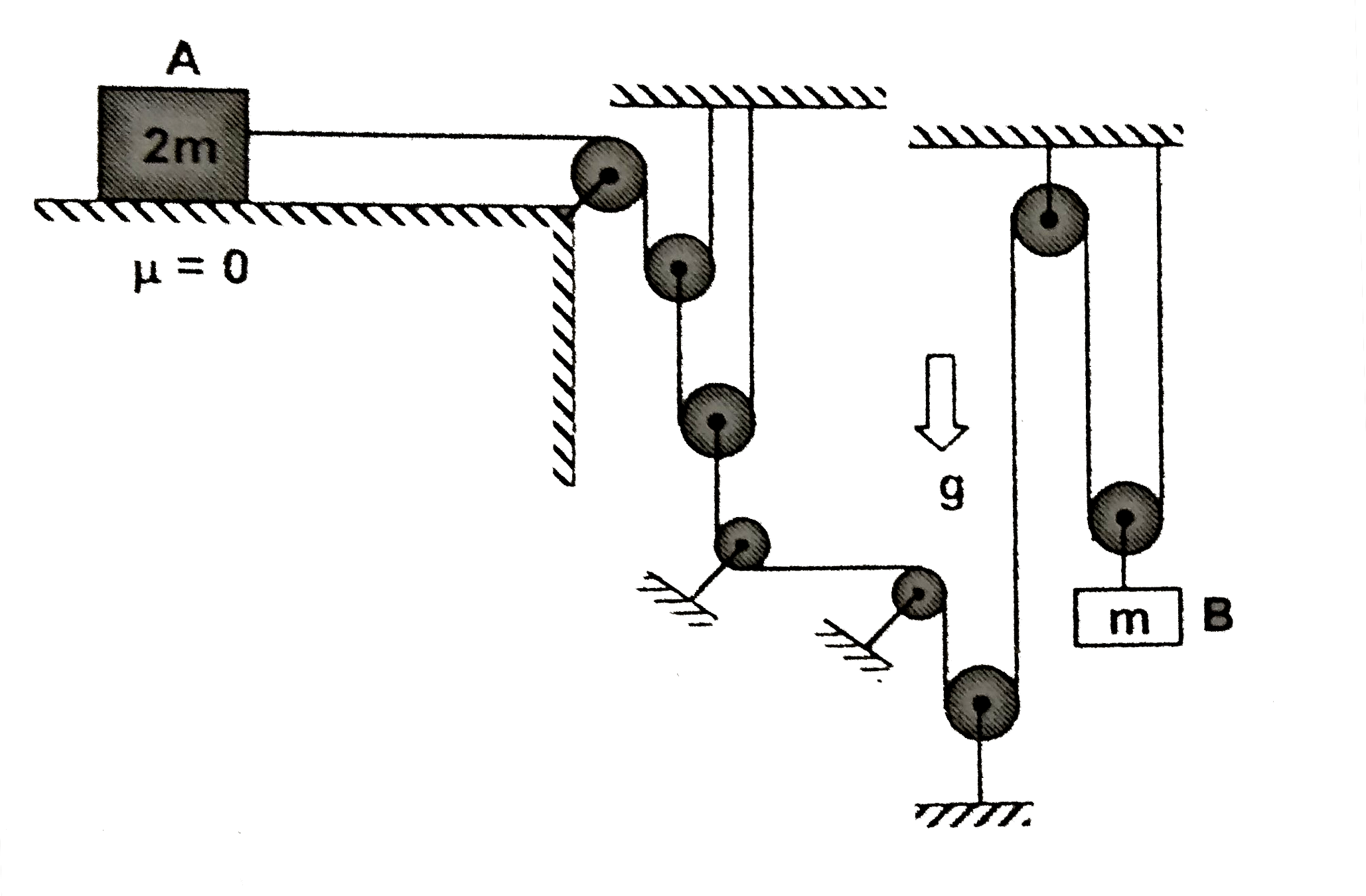
An ideal string pulley system is shown in the figure and system is released from rest choose correct optionView SolutionIn the pulley-block system shown in figure, strings are light. Pulleys are massless and smooth. System is released from rest. In 0.3 seconds.
 . View Solution
All surfaces shown in figure are smooth. System is released from rest. x and y comonents of acceleration of COM are
 View Solution
In the arrangement shown in fig., all pulleys are smooth and massless. When the system is released from the rest, acceleration of block 2 and 3 relative to 1 are 1ms−2 downwards and 5ms−2 downwards, respectively. Acceleration of block 3 relative to 4 is zero.
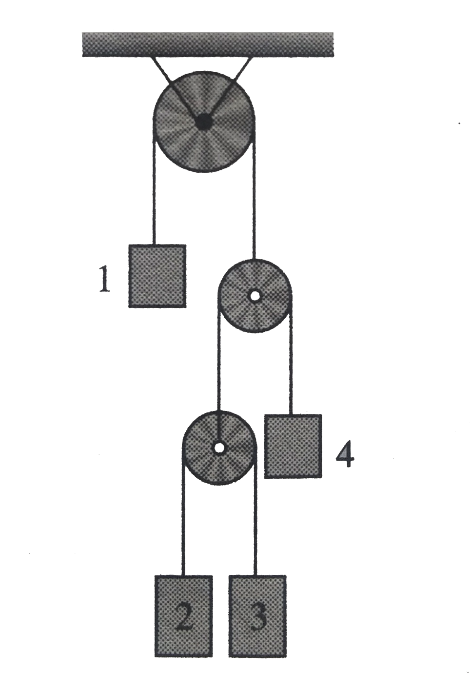
Find the absoulte acceleration of block 2.View SolutionIn the arrangement shown in fig., all pulleys are smooth and massless. When the system is released from the rest, acceleration of block 2 and 3 relative to 1 are 1ms−2 downwards and 5ms−2 downwards, respectively. Acceleration of block 3 relative to 4 is zero.
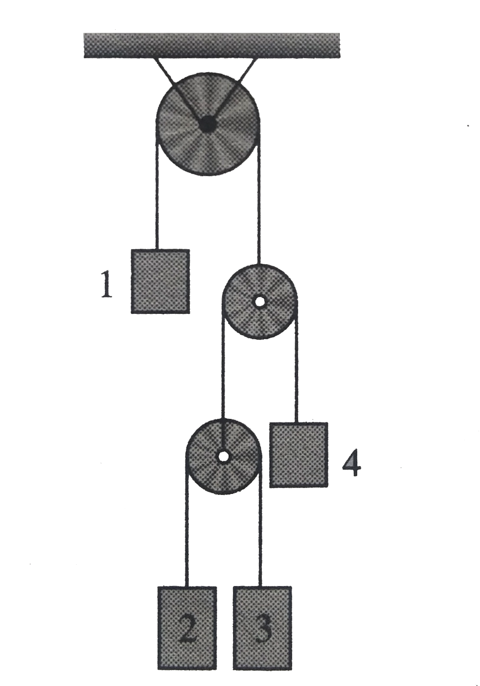
Find the absoulte acceleration of block 4.View SolutionIn the arrangement shown in fig., all pulleys are smooth and massless. When the system is released from the rest, acceleration of block 2 and 3 relative to 1 are 1ms−2 downwards and 5ms−2 downwards, respectively. Acceleration of block 3 relative to 4 is zero.
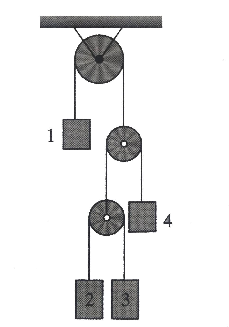
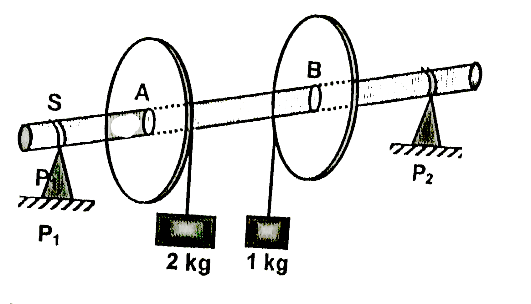
Find the absolute acceleration of block 1.View SolutionTwo discs A and B each of mass 2kg and radius 0.5m are rigidly fixed to the end of a thin shaft S, which is supported in horizontal position with the help of two smooth bearings at points P1 and P2. Two blocks of masses 2kg and 1kg are connected to the light cords wrapped around the discs as shown in the figure. There is no slipping between the cord and the discs. If the system is released from rest from the position shown, the mark released from rest from the position shown,
 View Solution
The intial configuration of the system is as shown in the figure.
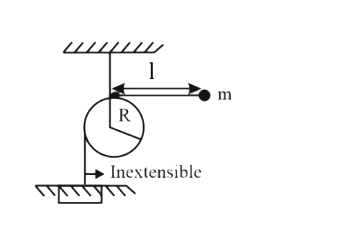
The string and the pulley are light. The bob is released and the string starts wrapping around the pulley. (The pulley is held in place by a force applied at the centre)
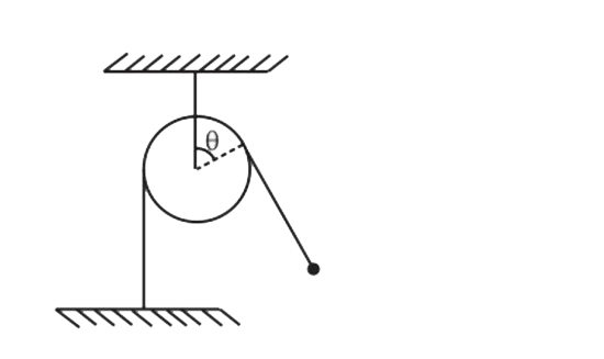
Find the rate r at which the length of the string warpped around the pulley increaes (as a function of θ).View Solution

