In a series L, R, C, circuit which is connected to a.c. source. When resonance is obtained then net impedance Z will be
Z=R
Z=ωL−1ωC
Z=ωL
Z=1ωC
The correct Answer is:A
To solve the problem of finding the net impedance Z in a series LRC circuit at resonance, we can follow these steps:
Step 1: Understand Resonance Condition
At resonance in a series LRC circuit, the inductive reactance XL is equal to the capacitive reactance XC. This can be expressed mathematically as:
XL=XC
Step 2: Write the Impedance Formula
The total impedance Z in a series LRC circuit is given by the formula:
Z=√R2+(XL−XC)2
where R is the resistance, XL is the inductive reactance, and XC is the capacitive reactance.
Step 3: Substitute the Resonance Condition
Since at resonance XL=XC, we can substitute this condition into the impedance formula:
Z=√R2+(XL−XC)2=√R2+(0)2
Step 4: Simplify the Expression
This simplifies to:
Z=√R2=R
Conclusion
Thus, the net impedance Z at resonance in a series LRC circuit is equal to the resistance R:
Z=R
At resonance in a series LRC circuit, the inductive reactance XL is equal to the capacitive reactance XC. This can be expressed mathematically as:
XL=XC
The total impedance Z in a series LRC circuit is given by the formula:
Z=√R2+(XL−XC)2
where R is the resistance, XL is the inductive reactance, and XC is the capacitive reactance.
Since at resonance XL=XC, we can substitute this condition into the impedance formula:
Z=√R2+(XL−XC)2=√R2+(0)2
This simplifies to:
Z=√R2=R
Thus, the net impedance Z at resonance in a series LRC circuit is equal to the resistance R:
Z=R
Similar Questions
Knowledge Check
Power dissipated in an L−C−R series circuit connected to an AC source of emf ε is
Aε2√R2+(ωL−1ωC)2RBε2[R2+(ωL−1ωC)2]RCε2R√R2+(ωL−1ωC)2Dε2R[R2+(ωL−1ωC)2]
An L-C-R series circuit , connected to a source E, is at resonance. Then,
View SolutionA series L-C-R circuit is operated at resonance . Then
View Solution(a) In a series LCR circuit connected across an AC source of variable frequency, obtain the expression for its impedance and draw a plot showing its variation with frequency of the AC source.
(b) What is the phase difference between the voltages across inductor and the capacitor at resonance in the LCR circuit ?
(c ) When and inductor is connected to a 200 V DC voltage, a current of 1Aflows trough it. when the same inductor is connected to a 200 V, 50 Hz AC source, only 0.5 A current flows. Explain, why ? Also, calculate the self inductance of the inductor.
View Solution(a) Deriver and expression for the average power consumed in a series LCR circuit connected to a.c., source in which the phase different between the voltage and the current in the circuit is ϕ.
(b) Define the quality factor in an a.c. circuit. Why should the quality factor have high value in receiving circuits ? Name the factors on which it depends.
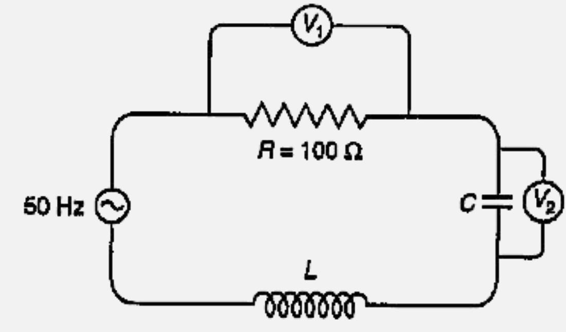
View SolutionFollowing figure shows a series RCL circuit connected to an a.c. source which generates an alternating emf of frequency 50 Hz. The reading of the voltmeter V1andV2 are 80 V and 60 V respectively.

Find :
(1) the current in the circuit.
(2) the capacitance C of the capacitor.
(ii) At resonance, what is the relation between impedance of a series LCR circuit and its resistance R?
View SolutionAn inductor wire has some resistnce R when connected to dc. It is connected to an ac source. Now the impedance of the wire will be more than R. (ture/false)
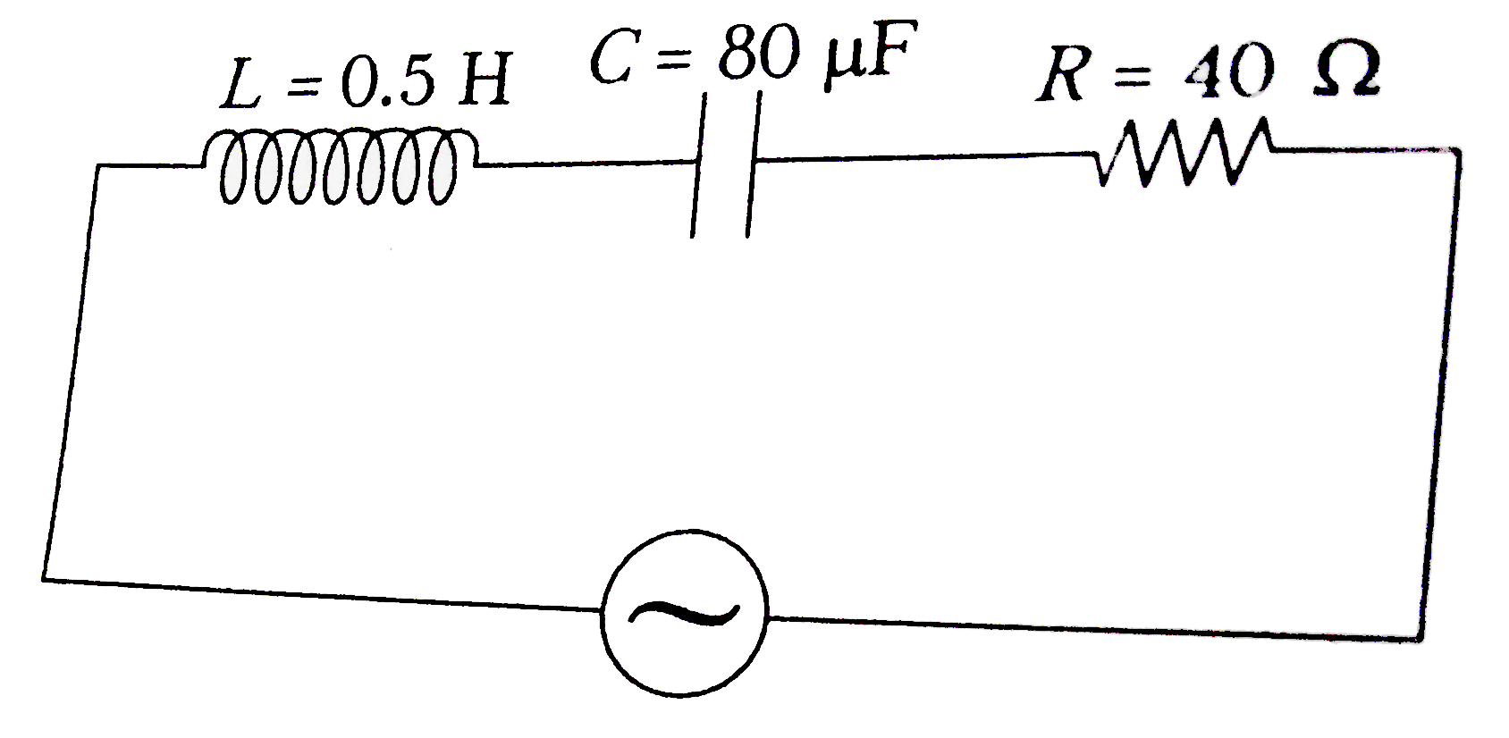
View SolutionIn the given figure , a series L-C-R circuit is connected to a variable frequency source of 230 V . The impedance and amplitude of the current at the resonating frequency will be

View Solution
