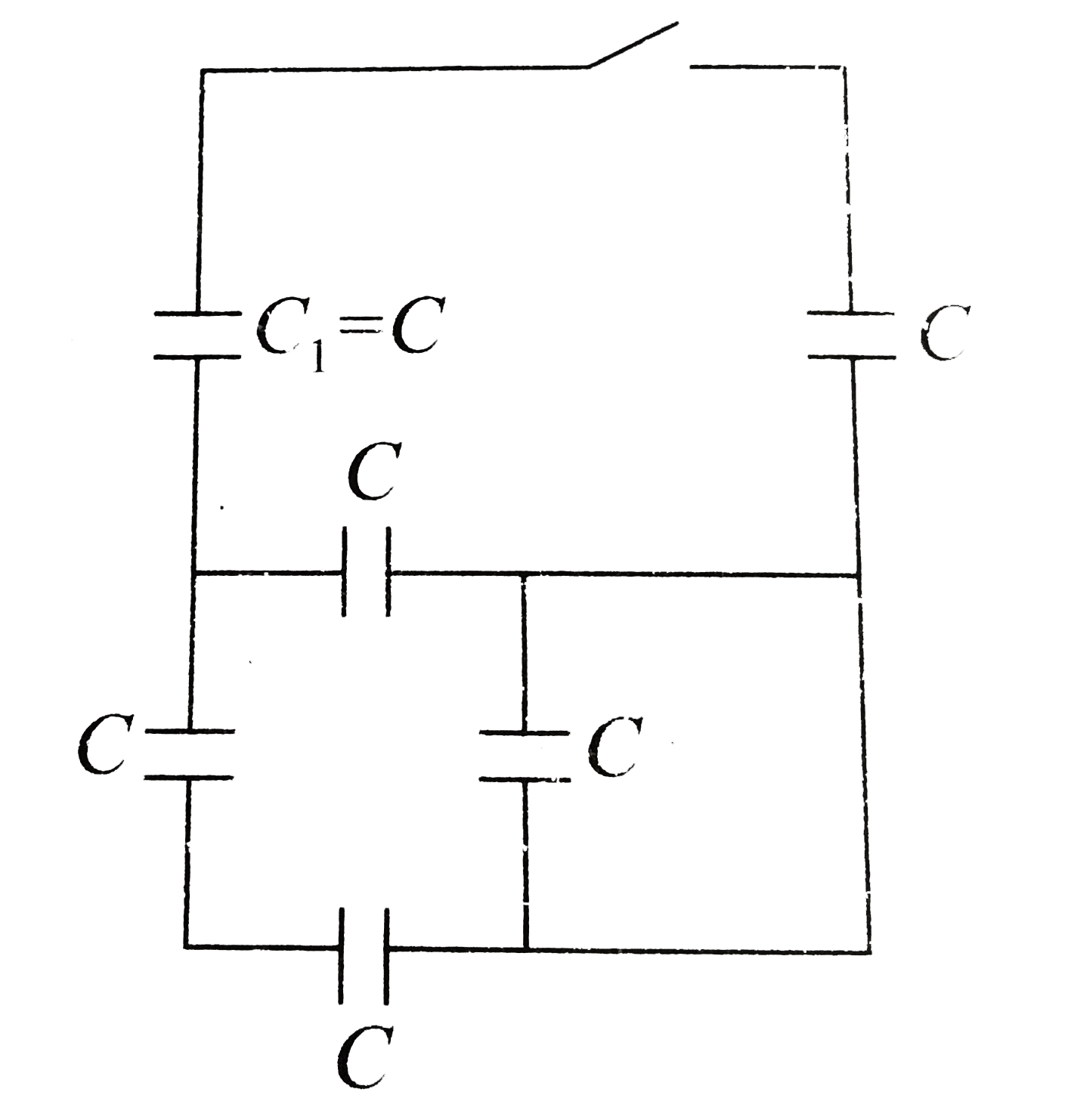
In the given figure switch is open initially and capacitor C2 is unchanged
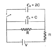
Charge on C2 just after closing the switch is
CV2
CV3
CV4
CV8
The correct Answer is:B
Step by step video & image solution for In the given figure switch is open initially and capacitor C_2 is unchanged Charge on C2 just after closing the switch is by Physics experts to help you in doubts & scoring excellent marks in Class 12 exams.
Updated on:21/07/2023Similar Questions
In the given figure switch is open initially and capacitor C2 is unchanged
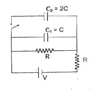
Energy in C1 is
View SolutionIn the given figure switch is open initially and capacitor C2 is unchanged
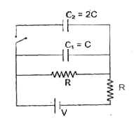
Potential difference on C1just after closing the switch is
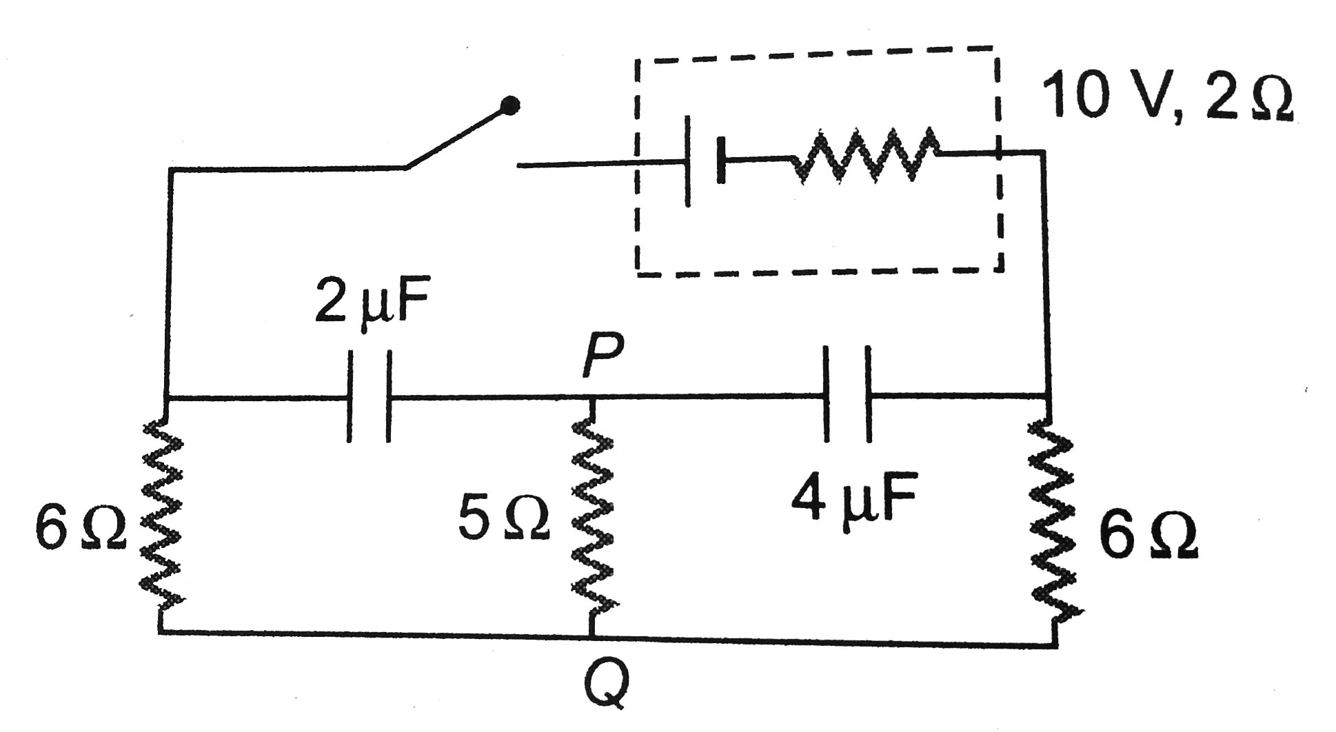
View SolutionIn the circuit shown in figure, the capacitors are initially uncharged. The current through resistor PQ just after closing the switch is
View Solution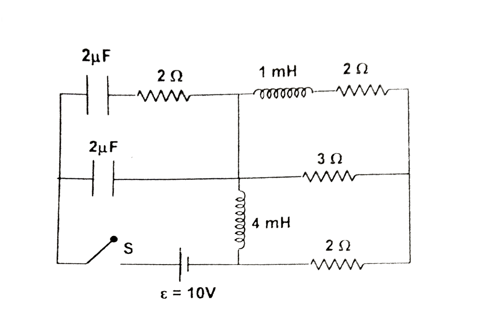
In the circuit shown, all the capacitors are initially uncharged. The current through the battery just after closing the switch 'S' is
View SolutionAssertion In the figure, just after closing the switch the potential drop across inductor is maximum.
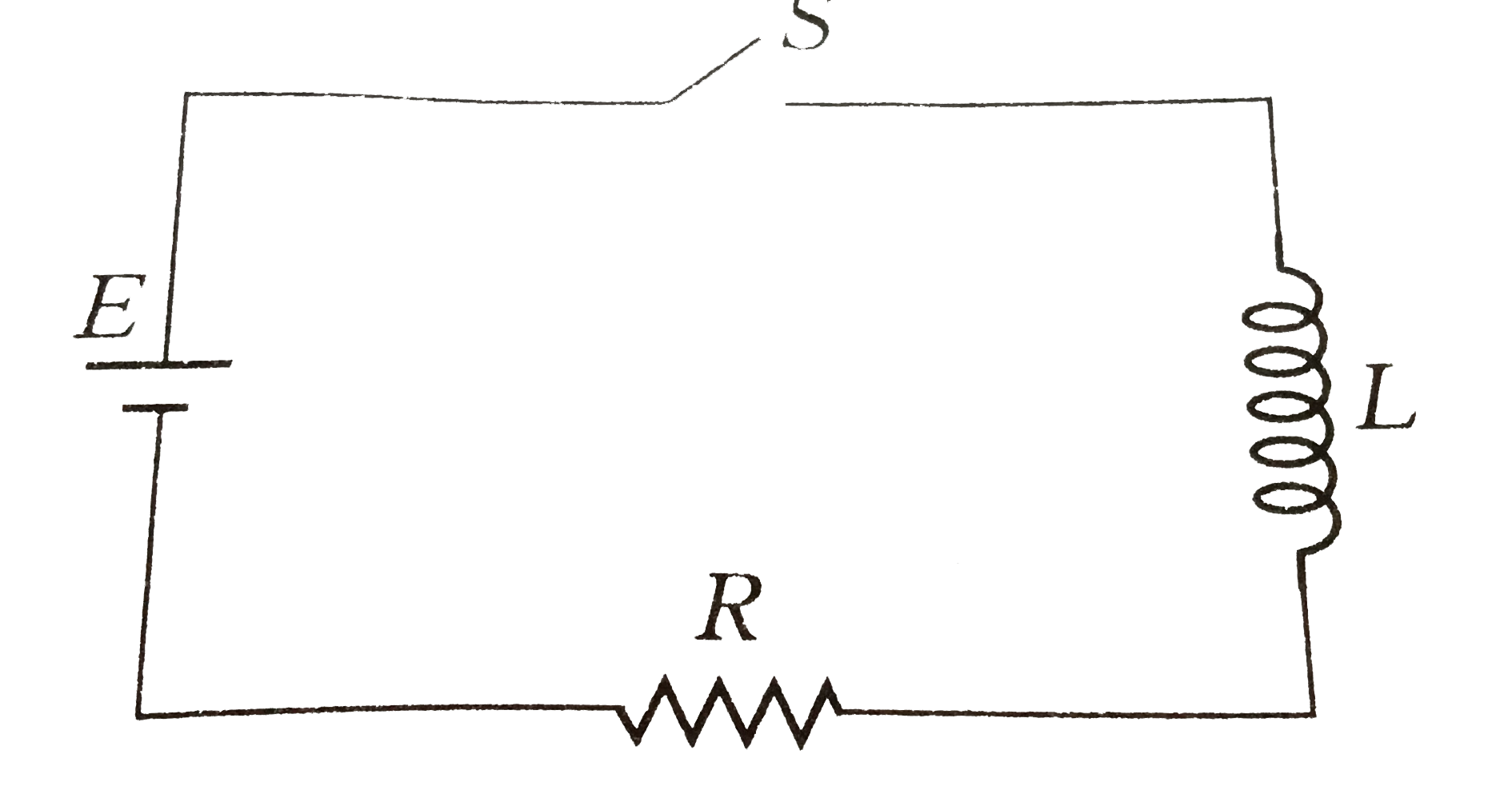
Reason The rate of change of current just after closing the switch is maximum.
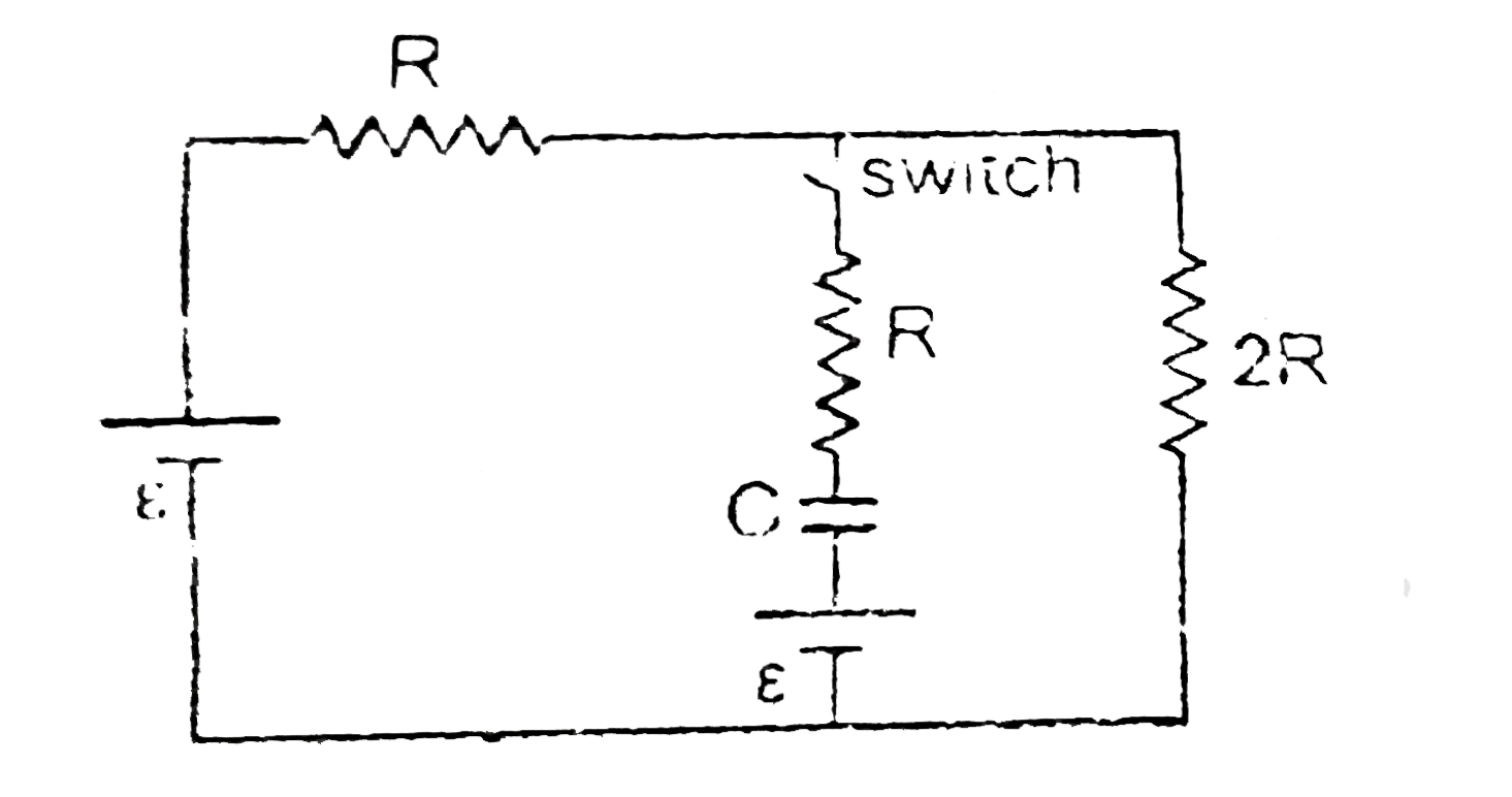
View SolutionInitially the capacitor was uncharged Current in the capacitor just after switching on will be ?
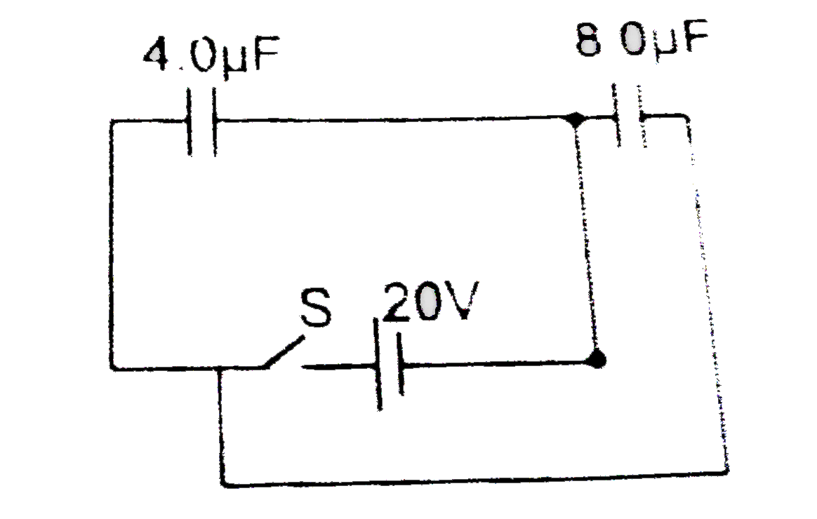
View Solution(i) Find the total charge flown through the battery in the arrangement shown in figure after switch S is closed (initially all the capacitors are uncharged).
(ii) Find out final charge on each capacitor.
View SolutionIn the circuit shown, all capacitors are identical. Initially, the switch is open and the capacitor marked C1 is the only one charged to a value Q0. After the switch is closed and the equilibrium is reestablished, the charge on the capacitor marked C1 is Q. Find the ratio initial change to final charge in capacitor C1.
View SolutionIn the connection shown in the figure, initially the switch K is open and the capacitor is uncharged. Then the switch is closed, and the capacitor is charged up to the steady state and the switch is opened again. Determine the values indicated by the values indicated by the ammeter just after closing the switch
[GivenV0=30V,R1=10kΩ,R2=5kΩ]
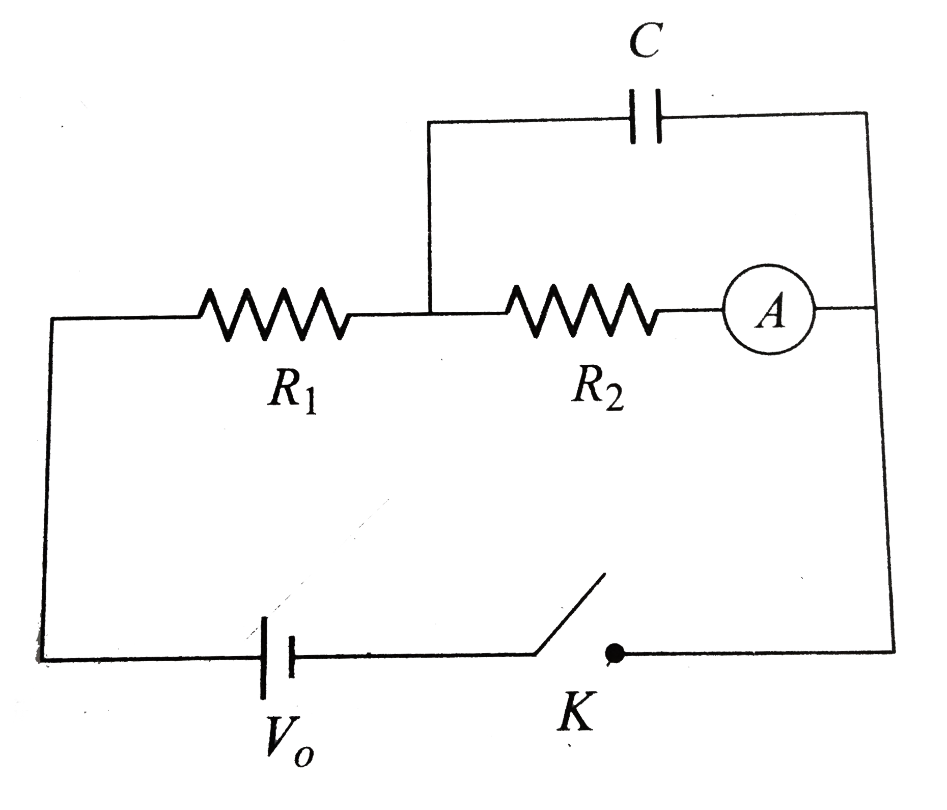 .
.
A long time after switch was closed.
View SolutionIn the connection shown in the figure, initially the switch K is open and the capacitor is uncharged. Then the switch is closed, and the capacitor is charged up to the steady state and the switch is opened again. Determine the values indicated by the values indicated by the ammeter.
[GivenV0=30V,R1=10kΩ,R2=5kΩ]
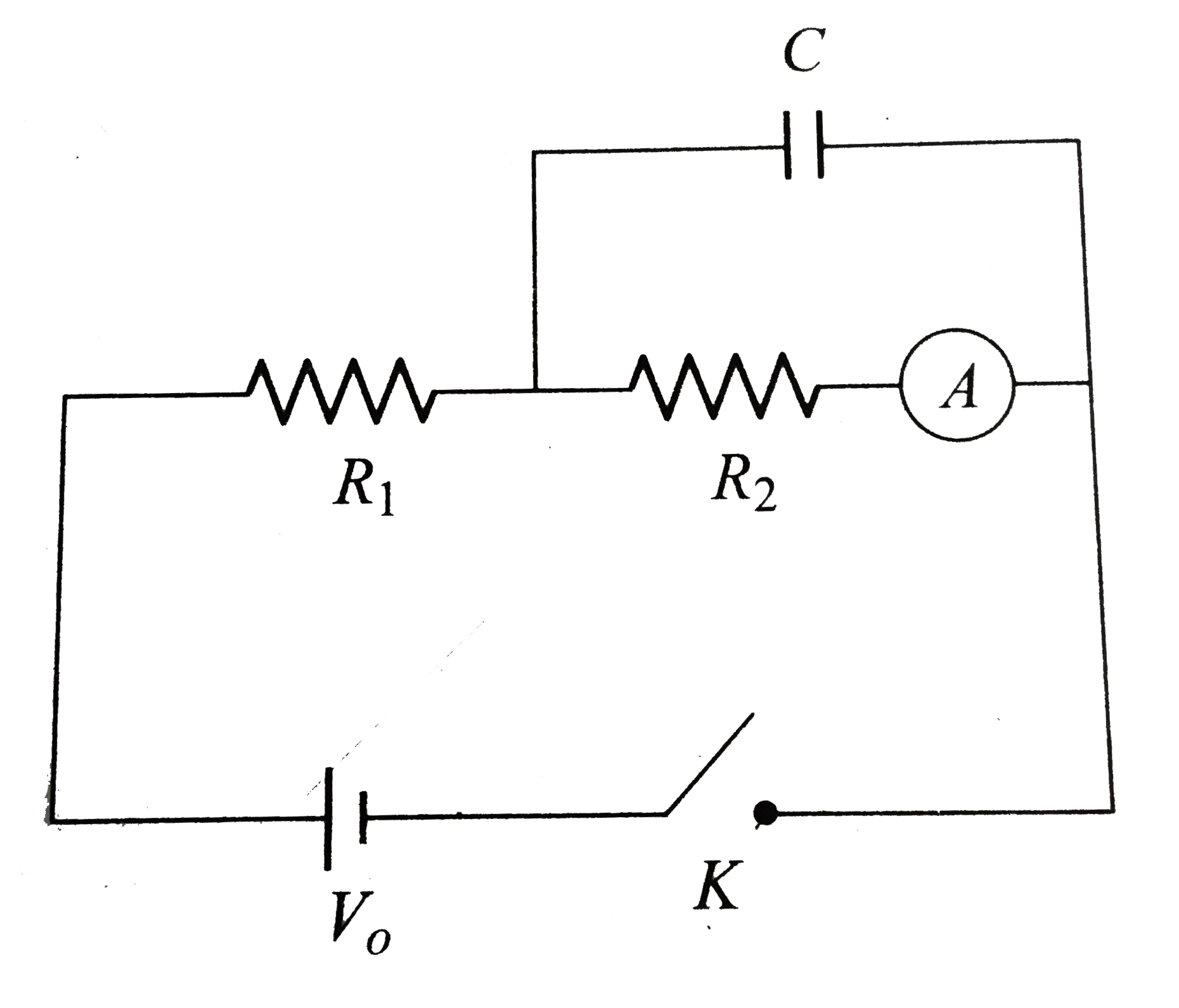 .
.
A long time after the switch was closed.
View Solution
