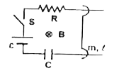
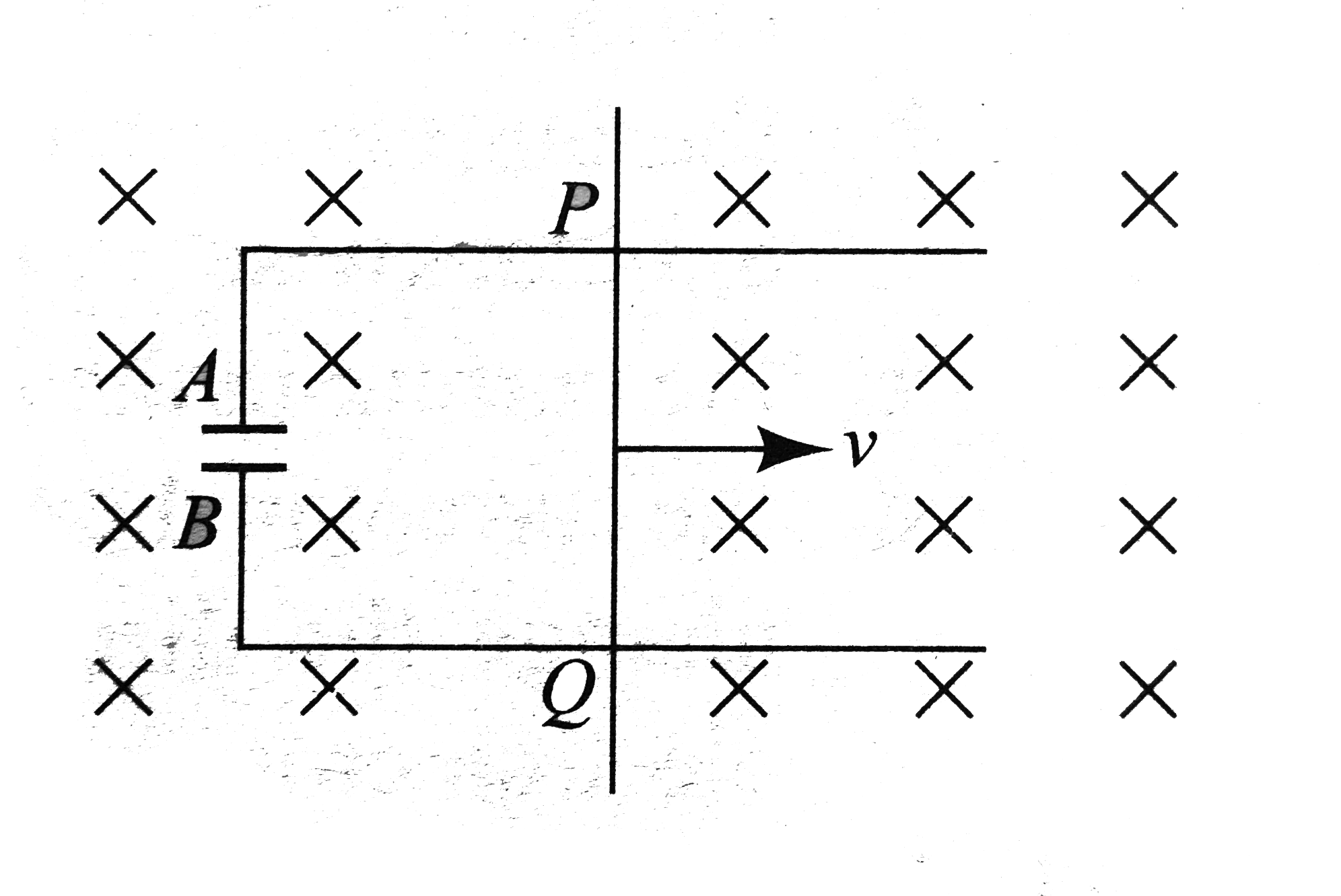
In the network shown, the connector of mass m, length l and negligible resistance can smoothly side along two fixed parallel rails. The capacitor is initially uncharged and ET a uniform magnetic field B exists in the region directed into the plane of paper. If the switch S is closed at t=0 then the charge on the capacitor after long time is
mcε2(B2l2c+m)
mcε(B2l2c+m)
2mcε(B2l2c+m)
3mcε2(B2l2c+m)
The correct Answer is:B
Step by step video & image solution for In the network shown, the connector of mass m, length l and negligible resistance can smoothly side along two fixed parallel rails. The capacitor is initially uncharged and ET a uniform magnetic field B exists in the region directed into the plane of paper. If the switch S is closed at t=0 then the charge on the capacitor after long time is by Physics experts to help you in doubts & scoring excellent marks in Class 12 exams.
Updated on:21/07/2023Similar Questions
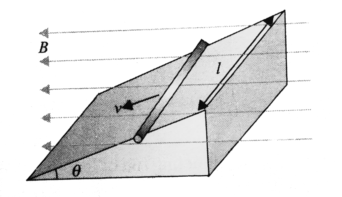
A rod of mass m, length l and resistance R is sliding down on a smooth inclined parallel rails with a cinstant velocity v. If a uniform horizontal magnetic field B exists, then find thevalue of B.
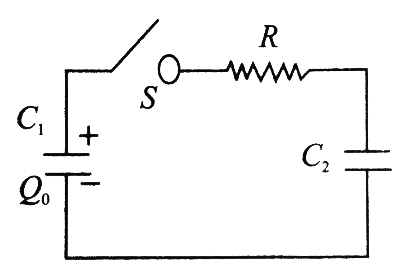
View SolutionIn the circuit shown, the capacitor C1 is initially charged with charge q0. The switch S is closed at time t = 0 . The charge on C2 after time t is
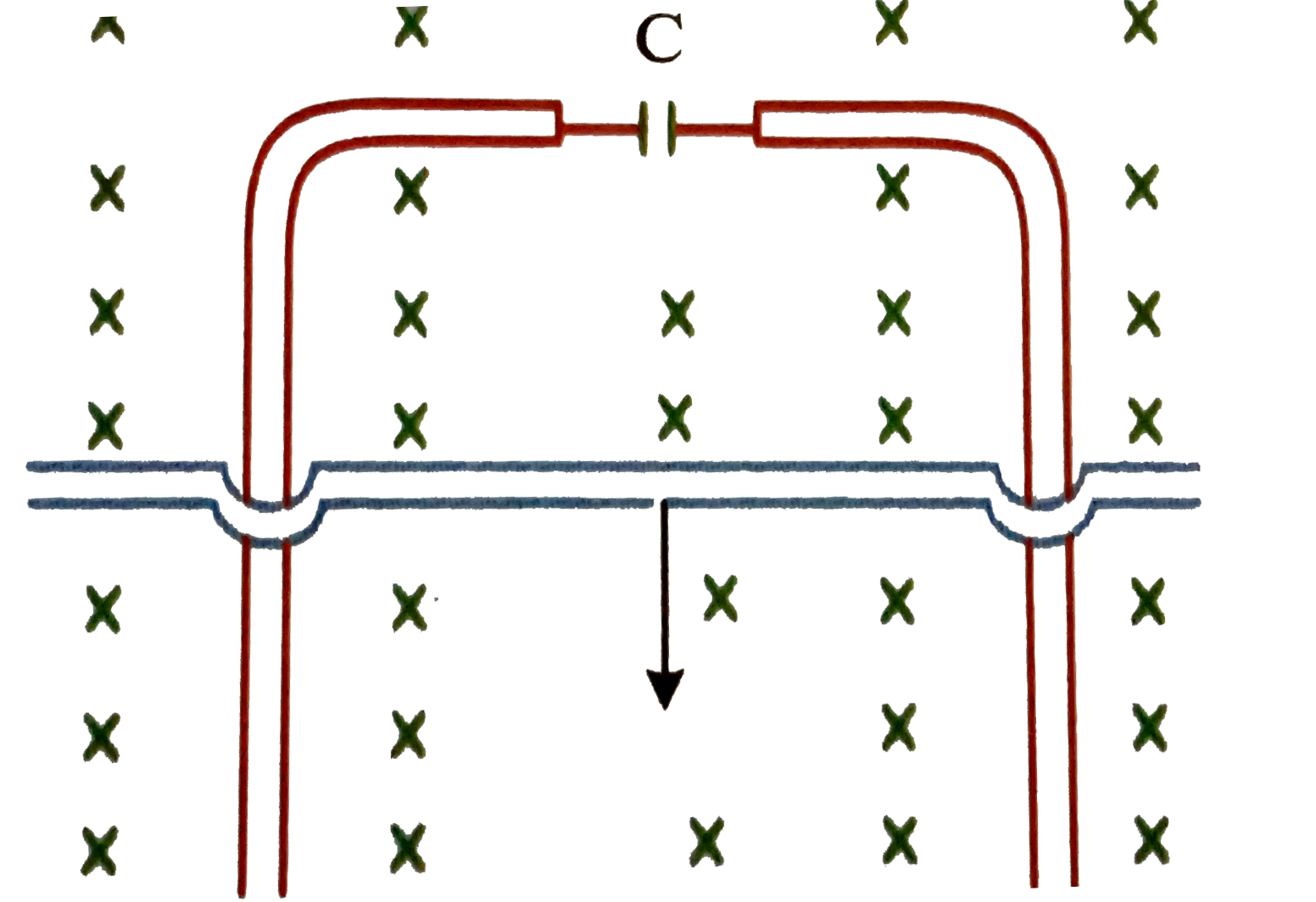
View SolutionA conductor of length l and mass m can slide without any friction along the two vertical conductors connected at the top through a capacitor. A uniform magnetic field B is set up ⊥ to the plane of paper. The acceleration of the conductor
View SolutionA copper wire ab of length l, resistance r and mass m starts sliding at t=0 down a smooth, vertical, thick pair of connected condcuting rails as shown in figure.A uniform magnetic field B exists in the space in a direction perpendicular to the plane of the rails which options are correct.
View SolutionFor the arrangement shown in the figure, the switch is closed at t=0. C2 is initially uncharged while C1 has a charge of 2μC
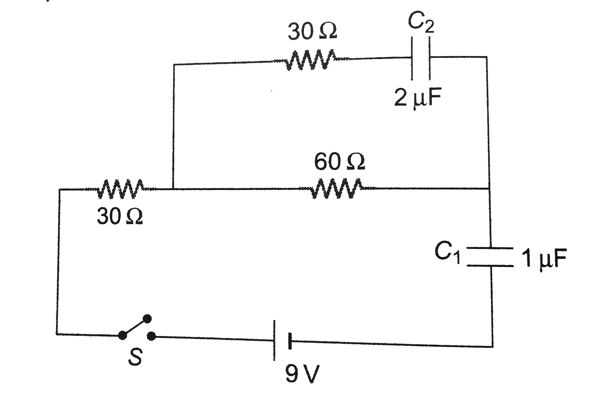
(a) Find the current comingn out of the battery just after the switch is closed.
(b) Find the charge on the capacitors in the steady state condition.
View SolutionA capacitor of capacitance Chas initial charge Q0 and connected to an inductor L as shown. Att=0 switch S is closed. The current through the inductor when energy in the capacitor is three times the energy of inductor is

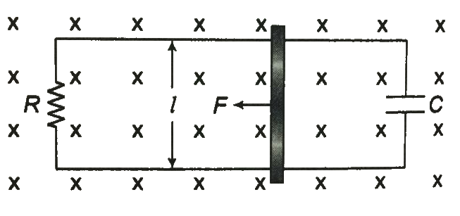
View SolutionTwo parallel long smooth conducting rails separated by a distance l are connected by a movable conducting connector of mass m. Terminals of the rails are connected by the resistor R and the capacitor C as shown in figure. A uniform magnetic field B perpendicular to the plane of the rail is switched on. The connector is dragged by a constant force F. Find the speed of the connector as a function of time if the force F is applied at t=0. Also find the terminal velocity of the connector.
View Solution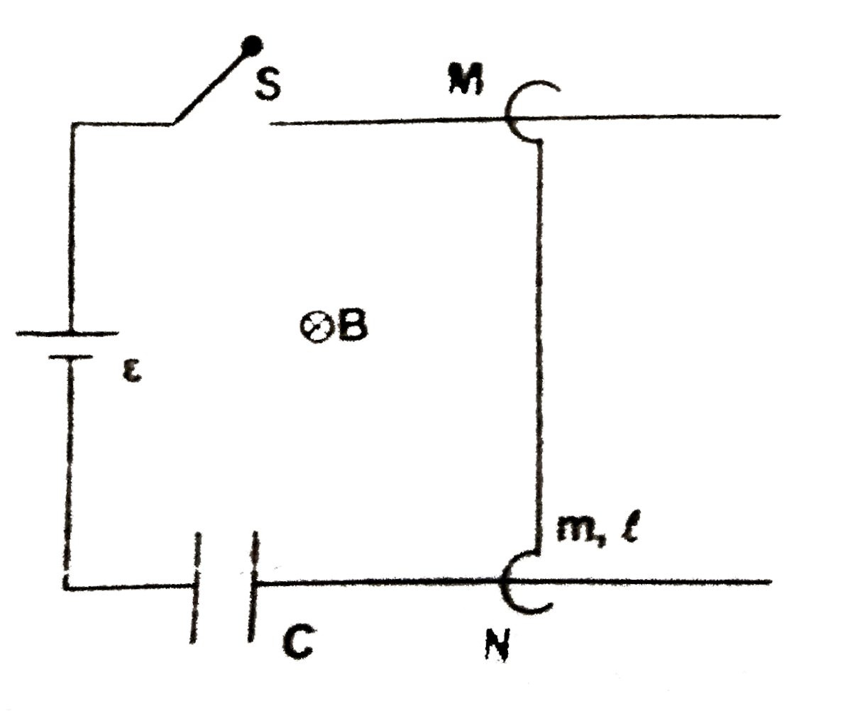
A conducting rod MN of mass m and length 'l' is placed on parallel smooth conducting rails connected to an uncharged capacitor of capacitance C and a battery of emf ε as shown. A uniform magnetic field B is existing perpendicular to the plane of the rails. The steady state velocity acquired by the conducting rod MN after closing switch S is (neglect the resistance of the parallel rails and the conducting rod)
View SolutionA conducting rod PQ of length L=1.0m is moving with a uniform speed v=2.0ms−1 in a uniform magnetic field B=4.0T directed into the plane of the paper.
A capacitor of capacity C=10μF is connected as shown in , then
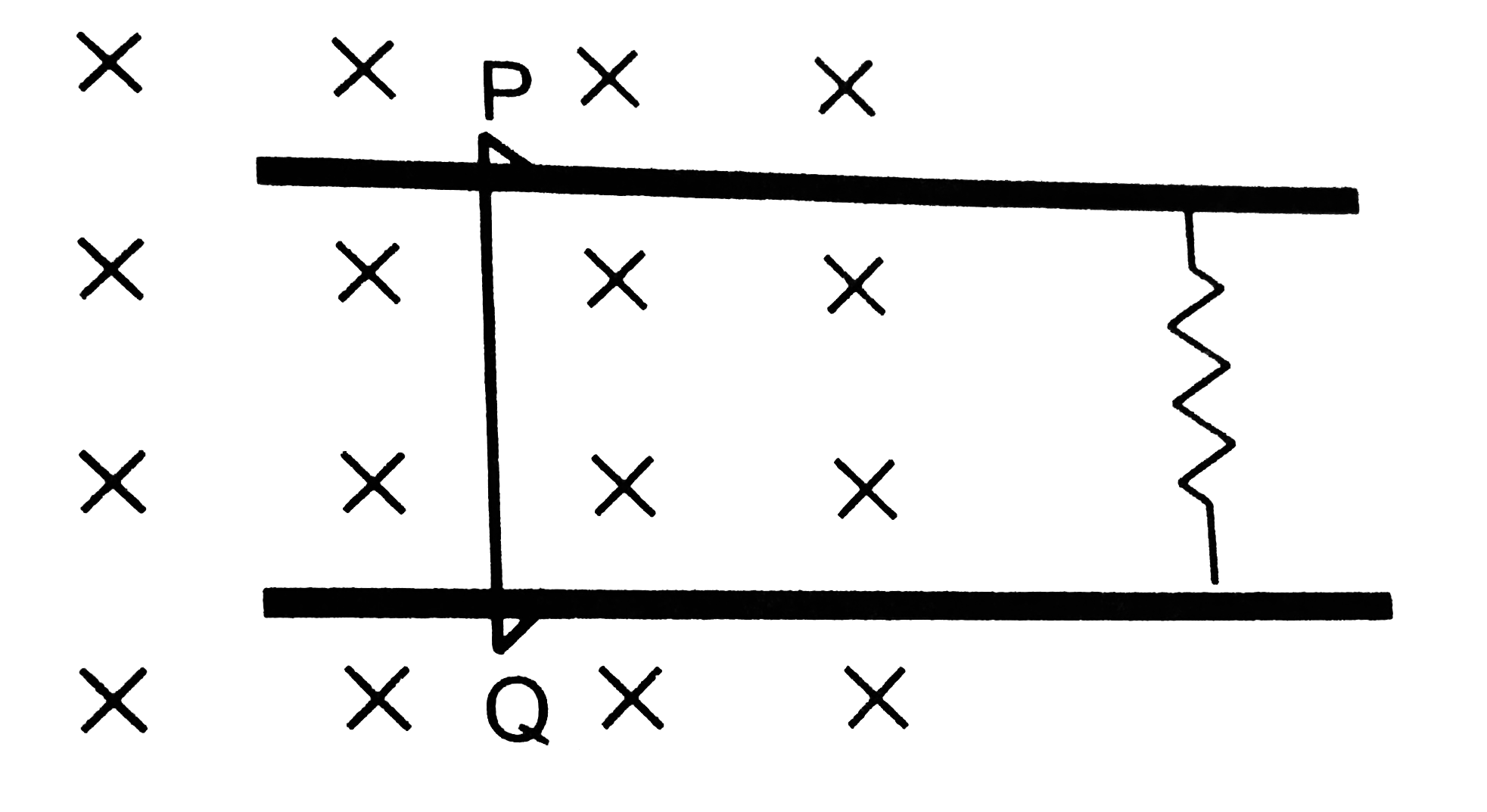
View SolutionConsider the situation shown in . The wire PQ has mass m, resistance r and can slide on the smooth, horizontal parallel rails separted by a distance l. The resistance of the rails is negligible. A uniform magnetic field B exists in the rectangualr region and a resistance R connects the rails outsided the field region At t= 0, the wire PQ is puched towards right with a speed v0. find (a) the current in the loop at an instant when the speed of the wire PQ is v, (b) the acceleration of the wire at this instatn, (c ) the velocity v as a function of x and (d) the maximum distance the wire will move.
View Solution
