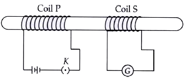
Two coils of insulated copper wire are wound over a non conducting cylinder as shown. Coil I has larger number of turns.
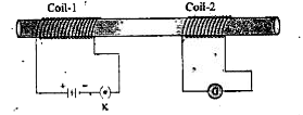
Write your observations when, (a). key K is closed, (b) key K is opened
(a) A momentary deflection is shown by the gaļvanometer.
(b) A momentary deflection is shown by the galvanometer but in the opposite direction.
Similar Questions
Two coils of insulated copper wire are wound over a non-conducting cylinder as shown. Coil 1 has comparative large number of turns. State your observations, when
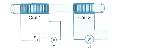
(i) Key K is closed. (ii) Key K is opened
Give reason for each of your observations.
View SolutionTwo circular coils-1 and coil-2 are kept close to each other as shown in the diagram. Coil-1 is connected to a battery and key and coil-2 with a galvanometer. State your observation in the galvanometer:
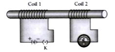
(a) When key K closed.
(b) When key K is opened, Give reason for your observations.
View Solution
Knowledge Check
In the given diagram, two coils of insulated copper wire are wound over a nonconducting cylinder as shown. Coil P has larger number of turns.
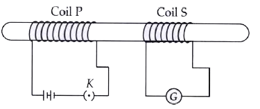
A momentary deflection is shown by the galvanometer , when:AKey K is openBKey K is closedCIn both the situationsDIn neither of the case.In the given diagram, two coils of insulated copper wire are wound over a nonconducting cylinder as shown. Coil P has larger number of turns.
In above phenomenon, the current is induced in another conductor,ABy changing magnetic fieldBBy increasing the strength of currentCBy decreasing the strength of the currentDBy using extra wireIn the given diagram, two coils of insulated copper wire are wound over a nonconducting cylinder as shown. Coil P has larger number of turns.
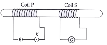
Which phenomenon is involved in it?AElectromagnetic inductionBMagnetismCElectromagnetismDNone of these
Two coils A and B are wound on the same iron core as shown in figure. The number of turns in the coil A and B are NA and NB respectively. Identify the correct statement
View SolutionIn the arrangement shown in figure, there are two coils wound on a non-conducting cylindrical rod. Initially the key is not inserted. Then the key is inserted and later removed. Then:
View SolutionIn the given diagram, two coils of insulated copper wire are wound over a nonconducting cylinder as shown. Coil P has larger number of turns.
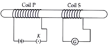
Flemings right hand rule explains:
View SolutionIn the given diagram, two coils of insulated copper wire are wound over a nonconducting cylinder as shown. Coil P has larger number of turns.
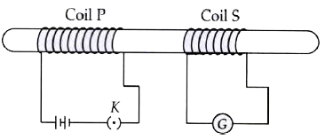
The rule which helps us to know direction of induced current:
View SolutionIn the arrangement shown in figure, there are two coils wound on a non-conducting cylindrical rod. Initially the key is not inserted. Then the key is inserted and later removed. Then:
View Solution
