Two coils of insulated copper wire are wound over a non conducting cylinder as shown. Coil I has larger number of turns.

Name the two coils used in this experiment.
Primary coil - coil I
Secondary coil - coil II
Similar Questions
Two coils of insulated copper wire are wound over a non-conducting cylinder as shown. Coil 1 has comparative large number of turns. State your observations, when
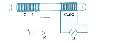
(i) Key K is closed. (ii) Key K is opened
Give reason for each of your observations.
View SolutionTwo coils A and B are wound on the same iron core as shown in figure. The number of turns in the coil A and B are NA and NB respectively. Identify the correct statement
View Solution
Knowledge Check
In the given diagram, two coils of insulated copper wire are wound over a nonconducting cylinder as shown. Coil P has larger number of turns.
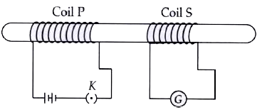
In above phenomenon, the current is induced in another conductor,ABy changing magnetic fieldBBy increasing the strength of currentCBy decreasing the strength of the currentDBy using extra wireIn the given diagram, two coils of insulated copper wire are wound over a nonconducting cylinder as shown. Coil P has larger number of turns.
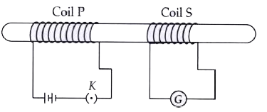
Which phenomenon is involved in it?AElectromagnetic inductionBMagnetismCElectromagnetismDNone of theseIn the given diagram, two coils of insulated copper wire are wound over a nonconducting cylinder as shown. Coil P has larger number of turns.
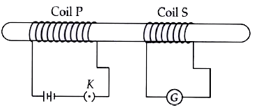
Flemings right hand rule explains:ADirection of magnetic fieldBDirection of motion of conductorCOnly (a)DBoth (a) and (b)
A coil of insulated copper wire is connected to a galvanometer. What would happen if a bar magnet is pushed into the coil?
View SolutionA coil of insulated copper wire is wound around a piece of soft iron and current is passed in the coil from a battery. What name is given to the device so obtained ? Give one use of the device mentioned by you.
View SolutionIn the given diagram, two coils of insulated copper wire are wound over a nonconducting cylinder as shown. Coil P has larger number of turns.
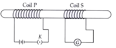
A momentary deflection is shown by the galvanometer , when:
View SolutionIn the given diagram, two coils of insulated copper wire are wound over a nonconducting cylinder as shown. Coil P has larger number of turns.
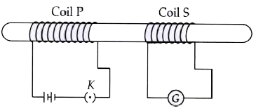
The rule which helps us to know direction of induced current:
View SolutionAssertion (A) : When two coils of enamelled copper wire are wound on each other, the mutual inductance between the coils is maximum.
Reason (R) : Mutual inductance does not depend on the orientation of the coils.
View Solution
