An electrical circuit is shown in Fig. The values ofresistances and the directions of the currents are shown. A voltmeter of resistance 400Ω is connected across the 400Ω. resistor. The battery has negligible internal resistance.
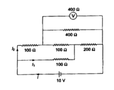
The value of current i1 is:
110A
120A
130A
140A
The correct Answer is:C
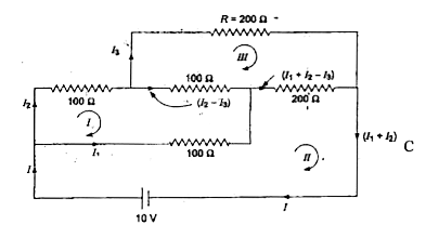
Resistance R=200Ω shown in the circuit is the equivalent resistance of the parallel combination of the 400Ω resistor and the resistance of 400Ω of the voltmeter.
Applying KirchhofFs loop rule to mesh I, we have
−100I2−100(I2−I3)+100I1=0
or I1−2I2+I3=0........(1)
Applying Kirchhoff.s loop rule to mesh II, we have
100I1−200(I1+I2+I3)+10=0
or 3I1+2I2−2I3−0.1=0.........(2)
Applying Kirchhoff.s loop rule to mesh III, we have
−200I3+200(I1+I2−I3)+100(I2−I3)=0
or 2I1+3I2−5I3=0........(3)
Simultaneous solution of Eqs. (1), (2) and (3) yields.
I1=I2=I3=130A
Similar Questions
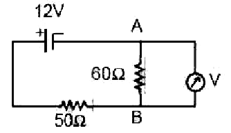
The voltmeter shown in fig, reads 6V across the 60Ω resistor. Then the resistance of the voltmeter is-
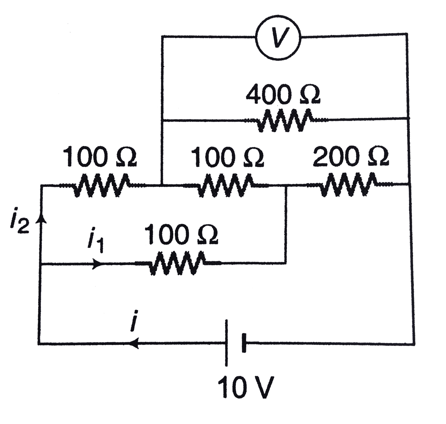
View SolutionAn electrical circuit is shown in figure. Calculate the potential difference across the resistor of 400Ω as will be measured by the voltmeter Vof resistance 400Ω either by applying Kirchhoff's rules or otherwise.
View Solution
Knowledge Check
Shows a network of eight resistors battery of resistance R(=2Ω) connected in a 3V battery of negligible internal resistance. The current I in the circuit is
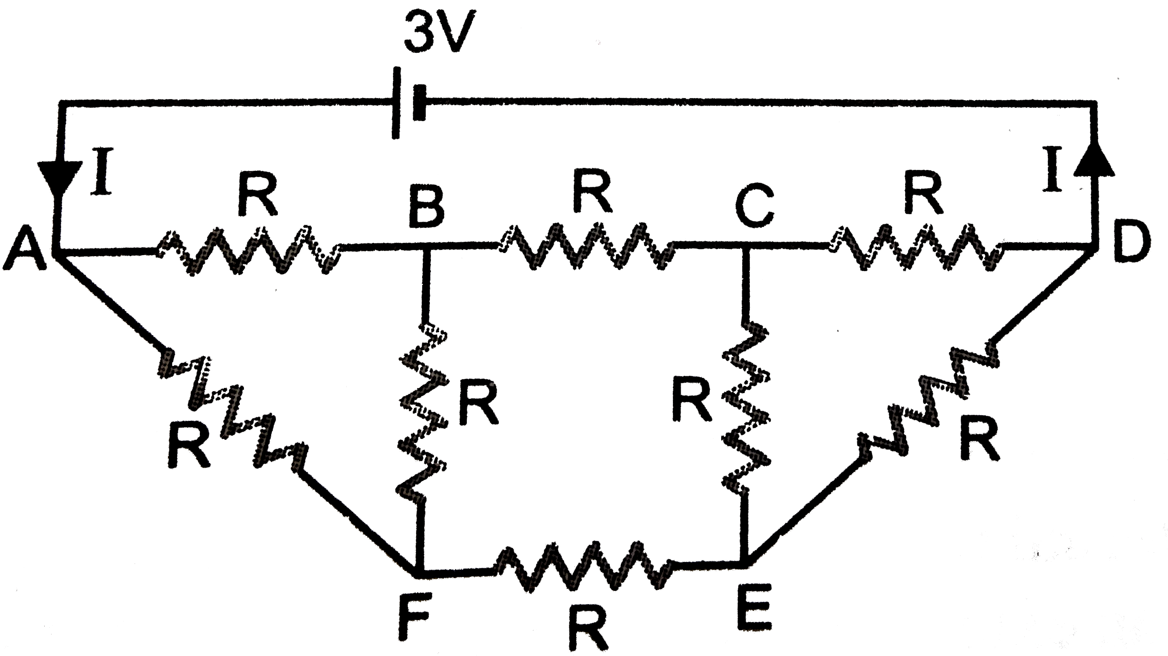 A0.25AB0.50AC0.75AD1.0A
Following figure shows a network of eight resistors, each equal to 2Ω , connected to a 3 V battery of negligible internal resistance. The current I in the circuit is :-
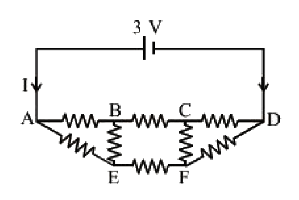 A0.25 AB0.50 AC0.75 AD1.0 A
Figure showns a network of eight resistors numbered 1 to 8, each equal to 2Ω, connected to a 3V battery of negligible internal resistance. The current l in the circuit is
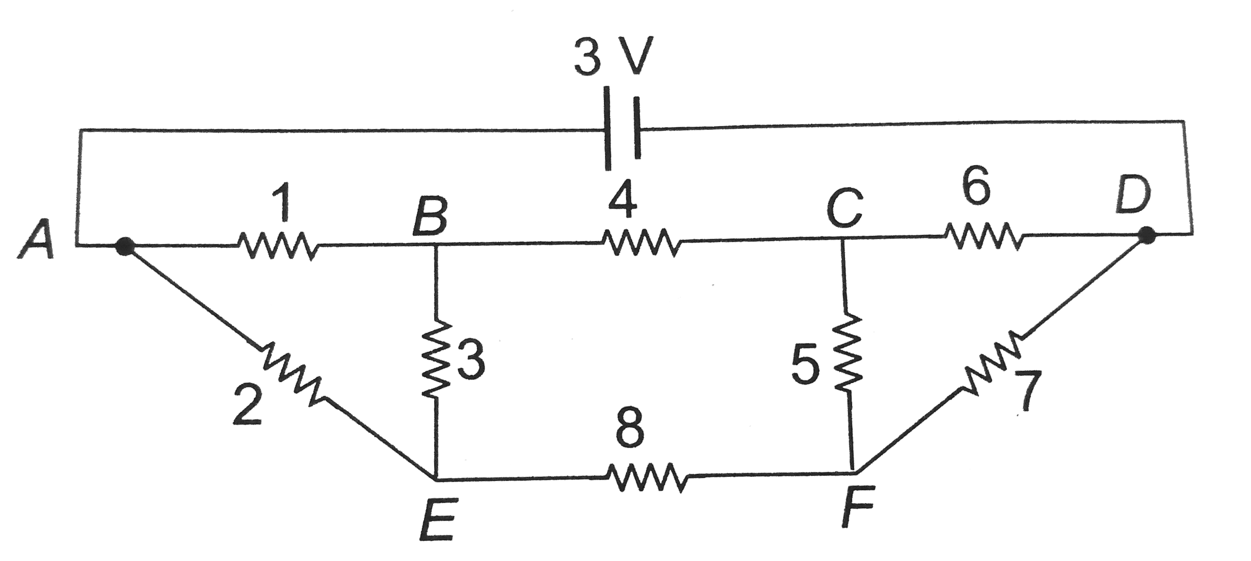 A0.25AB0.5AC0.75AD1.0A
An electrical circuit is shown in figure. Calculate the potential difference across the resistor of 400Ω as will be measured by the voltmeter Vof resistance 400Ω either by applying Kirchhoff's rules or otherwise.

View SolutionIn the circuit shown, reading of the voltmeter connected across 400Ω resistance is 60 V. If it is connected across 300Ω resistance then reading in volt will be
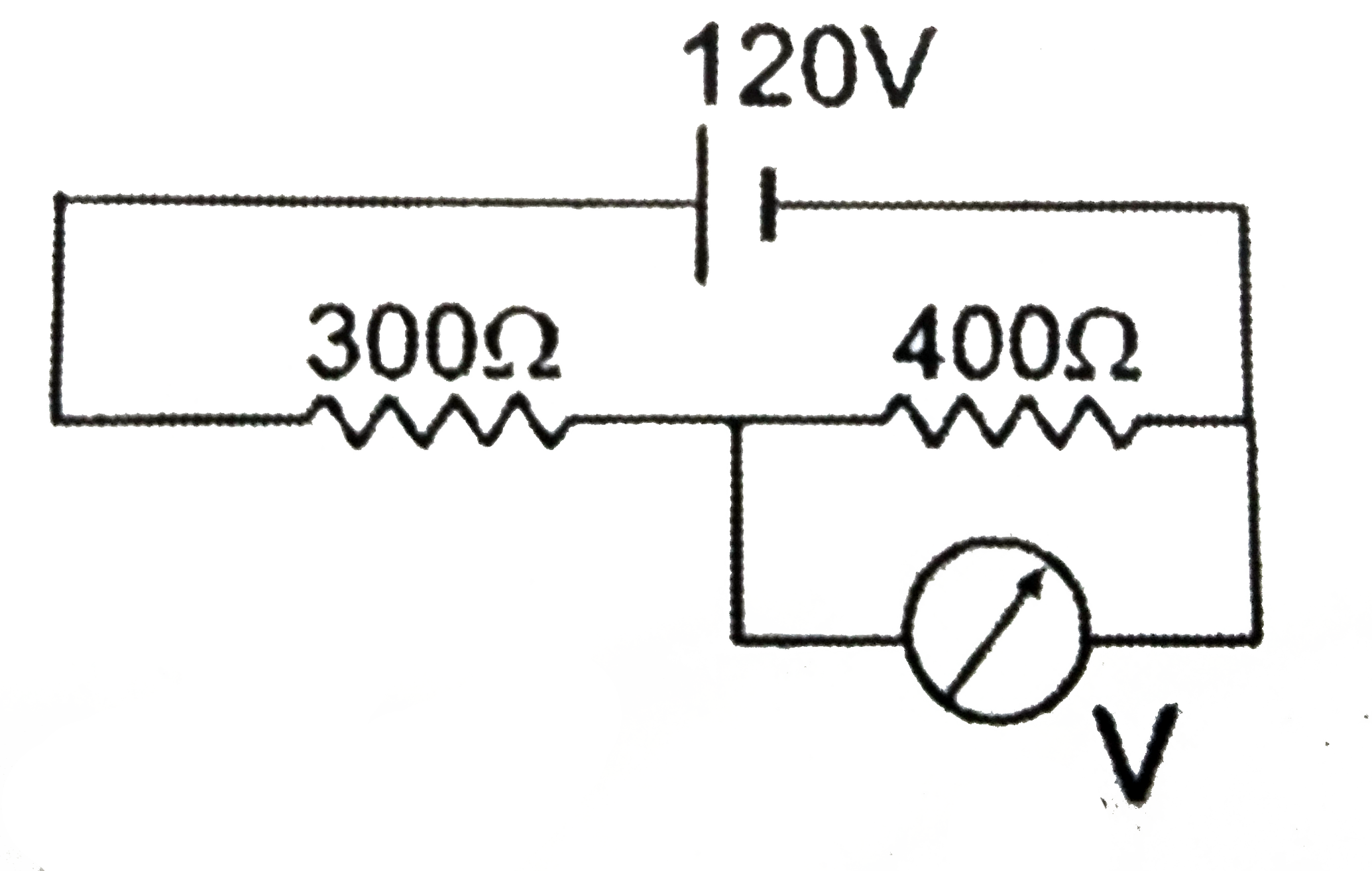
View SolutionIn the circuit shown, reading of the voltmeter connected across 400Ω resistance is 60 V. If it is connected across 300Ω resistance then reading in volt will be

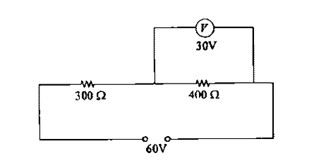
View SolutionIn the circuit diagram shown in Fig. 4.53, a voltmeter reads 30 V when connected across 400Ω resistance. Calculate what the same voltmeter reads when it is connected across 300Ω resistance.
View SolutionIn the circuit shown in figure-3 .3 89, the voltmeter reads 30V when it is connected across 400Ω resistance. Calculate what the same voltmeter will read when it is connected across the 300Ω resistance.
View Solution
